Productivity Lift.pdf - 第56页
5 Configuration User Manual - Productivity Lift Soko 00166631-01 / 12031477 5.2 Interface 1 Software version V 43.140 Edition April 2006 48 5.2 Interface 1 „Interface 1” defines the interface at th e inlet (n-1) to previ…

User Manual - Productivity Lift Soko 00166631-01 / 12031477 5 Configuration
Software version V 43.140 Edition April 2006 5.1 Language
47
5 Configuration
The configuration serves to set the required operating parameters. These are basic settings,
which need generally only be set during the initial system installation. These settings can be mod-
ified at a later date, but only by personnel with the relevant expertise.
Numerical values can be entered as follows using the cursor keys and the ALT key:
1. The ALT key can be used to move the flashing cursor to the position to be changed. The cursor
moves from left to right from position to position.
2. The cursor keys „V” and „W” can be used to increase or decrease the numerical value at the
relevant position.
If selection options are given in the menus, the cursor keys can be used to scroll through them in
both directions.
Data is only entered in the menus if the „Enter” key is pressed after modifying the settings. The
user is then taken automatically to the next menu. It is possible to return to the stand-by mode via
the last menu.
If entries are not confirmed, the „Start/Stop” key must be pressed instead of the „Enter” key.
In stand-by mode, the configuration menu is called up using the „V” and „ALT” keys. These keys
must be actuated immediately one after the other.
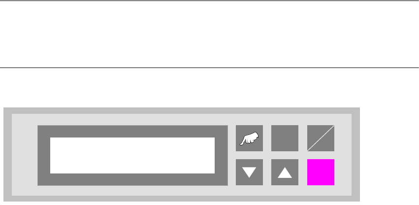
5.1 Language
This menu is used to set the language of the display. The options are German and English.
Fig. 5 - 1 Language
ALT
Enter
Start
Stop
Language
English
5 Configuration User Manual - Productivity Lift Soko 00166631-01 / 12031477
5.2 Interface 1 Software version V 43.140 Edition April 2006
48
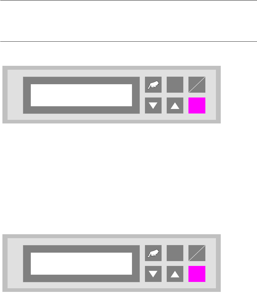
5.2 Interface 1
„Interface 1” defines the interface at the inlet (n-1) to previous systems.
The available settings are „SMEMA” and „Siemens”.
NOTE
The device is equipped with a defined interface. The interface shown in the display must conform
to the interface installed at the interface module AMI. It's possible to change the interface subse-
quently, but this may only be done by an authorised person.
Fig. 5 - 2 Interface 1
ALT
Enter
Start
Stop
Interface 1
Siemens
User Manual - Productivity Lift Soko 00166631-01 / 12031477 5 Configuration
Software version V 43.140 Edition April 2006 5.3 Interface 2
49
5.3 Interface 2
„Interface 2” defines the interface at the outlet (n+1) to subsequent systems.
The available settings are „SMEMA” and „Siemens”.
NOTE
The device is equipped with a defined interface. The interface shown in the display must conform
to the interface installed at the interface module AMI. It is possible to change the interface subse-
quently, but this may only be done by an authorised person.
Fig. 5 - 3 Interface 2
5.4 Wait period PCB
Time buffer for transferring a printed circuit board. Once this period has elapsed, the belt drive is
switched off and a fault indication is output since no PCB has arrived at the light barrier.
The unit of value is [0.01s] and the setting range is between 300 and 9999, which corresponds to
a time of 3 s to 99.99 s.
Fig. 5 - 4 Wait period PCB
ALT
Enter
Start
Stop
Interface 2
Siemens
ALT
Enter
Start
Stop
Wait period PCB
2000