X3_X4_Series machine.pdf - 第108页
3 Technical data User manual SIPLACE X-Series 3.4 Dimensions and weight of the placement mach ine Software Version SR. 601.xx 11/2005 US Edition 108 3.4.8 Maneuvering distance for the co mponent trolley on the X3 machine…
User manual SIPLACE X-Series 3 Technical data
Software Version SR.601.xx 11/2005 US Edition 3.4 Dimensions and weight of the placement machine
107
3.4.7 Maneuvering distance for the component trolley on the X4 machine
3
3
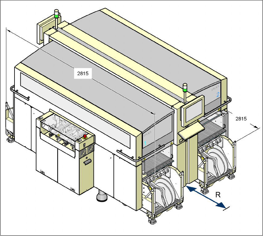
Fig. 3.4 - 6 Maneuvering distance for the component trolley on the X4 machine
The maneuvering distance R of the component trolley on the X4 machine is:
– 750 mm with the handles folded down
– 1050 mm with the handles folded up
3
3
3
3 Technical data User manual SIPLACE X-Series
3.4 Dimensions and weight of the placement machine Software Version SR.601.xx 11/2005 US Edition
108
3.4.8 Maneuvering distance for the component trolley on the X3 machine
3
3
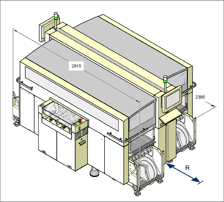
Fig. 3.4 - 7 Maneuvering distance for the component trolley on the X3 machine
The maneuvering distance R of the component trolley on the X3 machine is:
– at locations 1, 3 and 4
750 mm with the handles folded down or
1050 mm with the handles folded u,
– at location 2
600 mm with the handles folded down or
900 mm with the handles folded up.
User manual SIPLACE X-Series 3 Technical data
Software Version SR.601.xx 11/2005 US Edition 3.4 Dimensions and weight of the placement machine
109
3.4.9 Maneuvering distance for the component trolley on the X2 machine
3
3
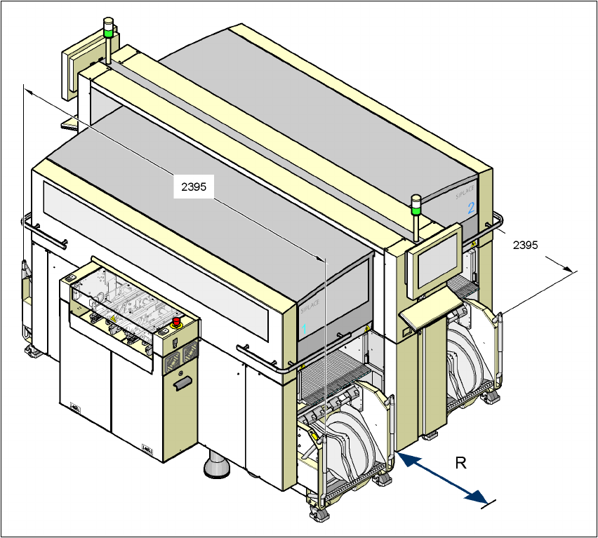
Fig. 3.4 - 8 Maneuvering distance for the component trolley on the X2 machine
The maneuvering distance R of the component trolley on the X2 machine is:
– at locations 2 and 4
600 mm with the handles folded down or
900 mm with the handles folded up
– at location 1 and 3
750 mm with the handles folded down or
1050 mm with the handles folded up.