X3_X4_Series machine.pdf - 第261页
User manual SIPLAC E X-Series 5 Tasks on the machine Software Vers ion SR.601.xx 11/ 2005 US Ed ition 5.4 Setting up the feeder m odules 261 Æ Check the " back" cen tering p in (item 3) of the f eeder mod ule a…
5 Tasks on the machine User manual SIPLACE X-Series
5.4 Setting up the feeder modules Software Version SR.601.xx 11/2005 US Edition
260
5.4.3.2 Using the X feeder module on the component table
5
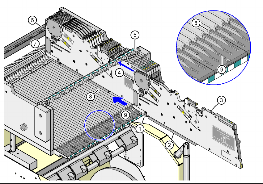
Fig. 5.4 - 3 Using the X feeder module on the component table
(1) Front slider guide for the X feeder module
(2) Back slider guide for the X feeder module
(3) "Back" centering pin on the X feeder module
(4) "Front" centering pin on the X feeder module
(5) Recesses in the centering bar for holding the "back" centering pin
(6) Centering holes on the component table for holding the "front" centering pin
(7) Locking latches
(8) Guide profile for the component table (Ω profile)
(9) Insertion aid for the feeder module
5
Æ Place the front slider guide (item 1) of the feeder module on the insertion aid (item 9) for the
component table.
Æ Hold the feeder module vertically and push it forward, along the guide profile (item 8). The
front (item 1) and rear (item 2) slider guides of the feeder module slide on the guide profile
(item 8).
Æ Carefully push the feeder module further until the "front" centering pin (item 4) is pushed into
the centering hole (item 6).

User manual SIPLACE X-Series 5 Tasks on the machine
Software Version SR.601.xx 11/2005 US Edition 5.4 Setting up the feeder modules
261
Æ Check the "back" centering pin (item 3) of the feeder module as you do so. This must slide
easily into the recess (item 5) in the centering bar, otherwise the feeder module is not seated
vertically on the component table or it was not placed on the guide profile (item 8) correctly.
Æ When the feeder module is at the stop position, the locking latch (item 7) latches on the lock-
ing roller of the feeder module (item 1 in Fig. 6.1 - 1
).
If you have forgotten to engage the removal handle (item 1 in Fig. 5.4 - 2
, page 259), the sta-
tus display on the feeder module's operator panel will light up red after a few seconds. The
LCD display contains the error message "Handle --->>" (see Fig. 5.6 - 1
, page 268). 5
Æ Engage the removal handle (item 1 in Fig. 5.4 - 2). The feeder module's status display
now lights up green and the feeder module is on standby. The track number and con-
veyor increment can be read on the LCD display once more.
5.4.4 Placing component tape on the X feeder module
5.4.4.1 Checking the X tape feeder module
Æ When you place the component tape in the feeder module, first check whether there are
any components in the vicinity of the pick-up window (item 2 in Fig. 5.4 - 5
).
Æ Remove any components that you find since they could cause a fault.
5.4.4.2 Preparing the component tape for insertion
Æ Check that there is a straight cut edge at the start of the component tape.
Æ If the transport holes are torn or bent, cut off this part of the tape.
Æ Also make sure that there are no streaks of adhesive on the cover foil.
Æ Pull around 30 cm cover foil away from the component tape if this does not expose any
components.
PLEASE NOTE 5
Use an SMD tape threader if there is insufficient cover foil available to make sure that no com-
ponents are lost:
for the 8 mm component tape: item no. 00355265-xx
for the 12 mm component tape: item no. 00356342-xx
Æ Shorten the component tape with the now exposed component pockets by around 3 cm.
Æ Remove the components from the open tape pockets.
Æ Wrap the cover foil around the front edge of the tape along the bottom of the tape.
5 Tasks on the machine User manual SIPLACE X-Series
5.4 Setting up the feeder modules Software Version SR.601.xx 11/2005 US Edition
262
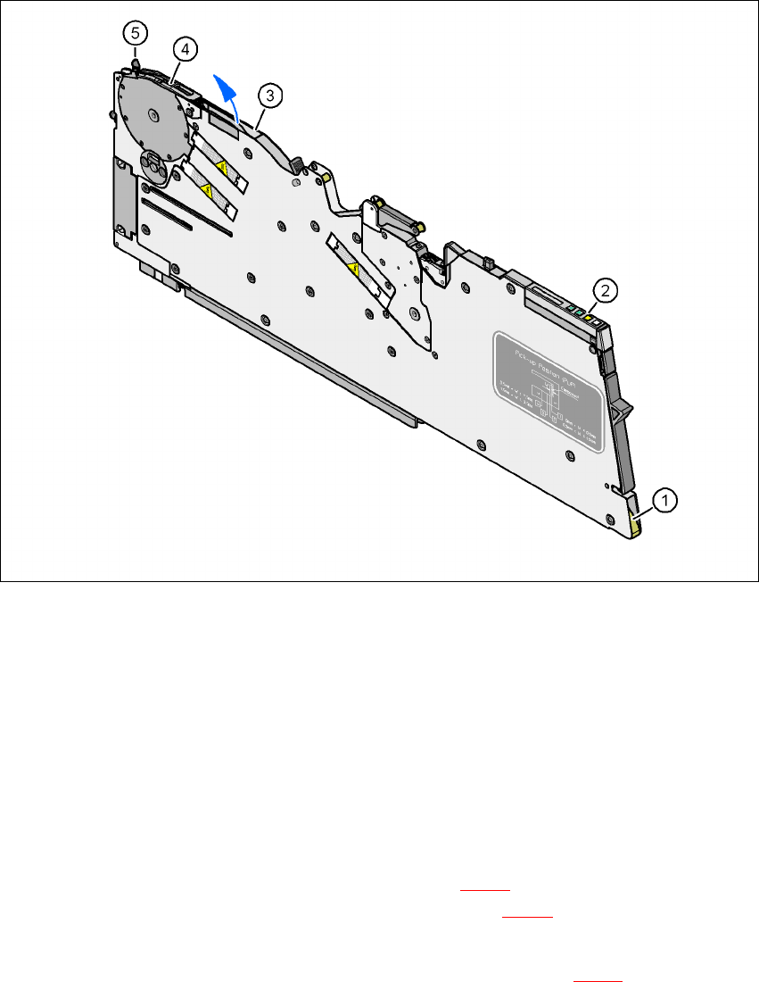
5.4.4.3 Inserting the component tape on the X feeder module
5
Fig. 5.4 - 4 Inserting the component tape
(1) Entry to the tape guide channel
(2) Operator panel
(3) Exit from the tape guide channel
(4) Pick-up window
(5) Lever for raising the pick-up window
5
Æ Hold the component tape so that the transport holes are on the left-hand side viewed in the
direction of travel.
Æ Push the component tape into the entry (item 1 in Fig. 5.4 - 4) to the tape guide channel and
further until it emerges from the exit opening (item 3 in Fig. 5.4 - 4
).
Æ Pull the component tape up and out, and fold the cover foil back against the top of the tape.
Æ Guide the start of the tape beneath the pick-up window (item 2 in Fig. 5.4 - 5) and further until
the component tape is touching the sprocket wheel.