X3_X4_Series machine.pdf - 第174页
4 Setting up and commissioning User manual SIPLACE X-Series 4.2 Delivery configuration and transport Sof tware Version SR.601.xx 11/2005 US E dition 174 4.2.1.2 W eight of the placement machine prep ared for disp atch Th…
User manual SIPLACE X-Series 4 Setting up and commissioning
Software Version SR.601.xx 11/2005 US Edition 4.1 Dimensions and weight of the placement machines
173
4 Setting up and commissioning
4.1 Dimensions and weight of the placement machines
Data for the dimensions and weight of the machine can be found in section 3.4, page 101.
4.2 Delivery configuration and transport
4.2.1 Transport packaging
Within Europe, the machine is supplied on a wooden pallet and wrapped in plastic film. Outside
Europe, the machine is supplied in a wooden crate mounted on a stable wooden pallet.
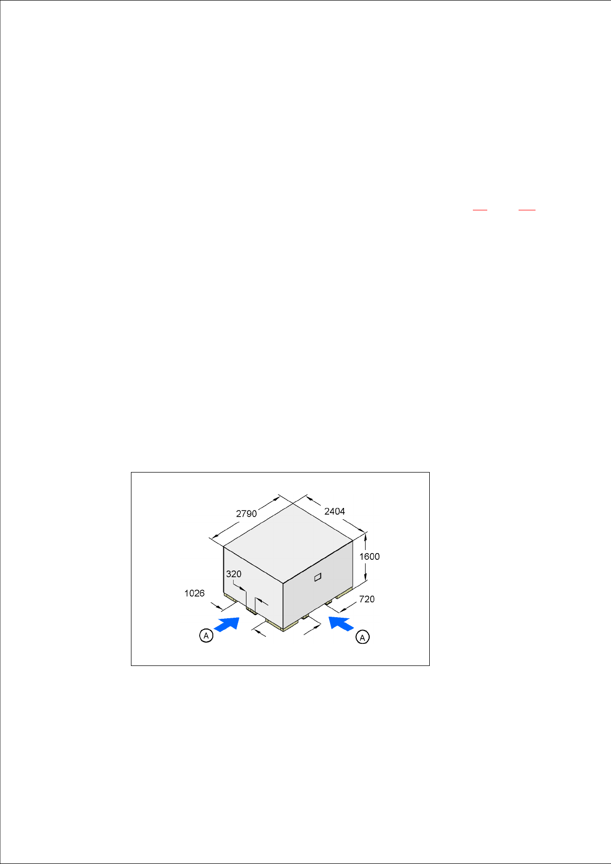
4.2.1.1 Dimensions of the transport packaging
The dimension of the wooden transport crate are as follows:
Length 2404 mm
Width 2790 mm
Height 1600 mm 4
4
Fig. 4.2 - 1 Transport crate - dimension in millimeters
(A) Fork-lift attachment points
4 Setting up and commissioning User manual SIPLACE X-Series
4.2 Delivery configuration and transport Software Version SR.601.xx 11/2005 US Edition
174
4.2.1.2 Weight of the placement machine prepared for dispatch
The following table contains the weights of the machines prepared for dispatch, including
packaging.
4
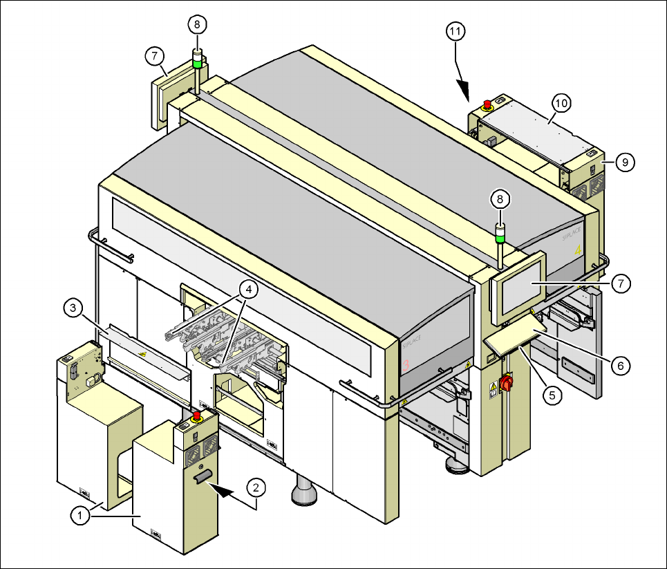
4.2.2 Configuration when delivered
The placement machine is configured as follows when delivered:
– The extension kit on the PCB output side (item 1 in Fig. 4.2 - 2
) is detached from the basic
machine and dismantled.
– The axis unit (item 2 in Fig. 4.2 - 2
) in the extension kit on the PCB output side is placed on
a transport cushion. All cables are attached to the axis unit.
– The track on the single conveyor is set to a width of 210 mm. On the dual conveyor, the width
of conveyor track 1 is 136 mm and conveyor track 2 is 210 mm. This width setting will be
important when fine-tuning the machine.
On the dual conveyor, the electrical plug-in connectors for the conveyor motor and light bar-
rier on the left-hand conveyor track are easily accessible and there is still enough space to fit
the output conveyor.
– The output conveyors (item 4 in Fig. 4.2 - 2
) of the single or dual conveyor are dismantled.
The electrical cables to the conveyor motors and light barriers are disconnected.
– Both keyboards (item 6 in Fig. 4.2 - 2
) are unplugged.
– The supporting plates for the keyboards (item 5 in Fig. 4.2 - 2
) are detached.
– Both monitors (item 7 in Fig. 4.2 - 2
) are dismantled.
– Both main fault indicators (item 8 in Fig. 4.2 - 2
) are dismantled.
– All the gantry axes are fixed with shipping braces.
Machine Dispatch within Europe Dispatch overseas
X2 3836 kg 4336 kg
X3 3920 kg 4420 kg
X4 4004 kg 4504 kg
User manual SIPLACE X-Series 4 Setting up and commissioning
Software Version SR.601.xx 11/2005 US Edition 4.2 Delivery configuration and transport
175
4
Fig. 4.2 - 2 Machine in the as-delivered configuration
(1) Extension kit on the PCB output side - Removed and dismantled for delivery
(2) Axis unit on the PCB output side - X4: gantries 2 and 3, X3: gantry 3, X3: gantries 1 and 3
(3) Conveyor cover
(4) Output conveyor
(5) Keyboard supporting plate
(6) Keyboard
(7) Monitor
(8) Main fault indicator
(9) Computer unit on the PCB input side
(10) Extension kit on the PCB input side - may be removed if necessary
(11) Axis unit on the PCB input side - X4 and X3: gantries 1 and 4