X3_X4_Series machine.pdf - 第290页
6 Component handling User manual SIPLACE X-Series 6.1 X feeder modules for the c omponent trolley fro m the SIPLACE X-series Software Version SR. 601.xx 11/2005 US Edition 290 6 Fig. 6.1 - 2 8 mm X tape feeder module - b…
User manual SIPLACE X-Series 6 Component handling
Software Version SR.601.xx 11/2005 US Edition 6.1 X feeder modules for the component trolley from the SIPLACE X-series
289
6.1.1.4 Design of the tape feeder module for the SIPLACE X-series
The two following diagrams show the design of the tape feeder module for the X-series with ref-
erence to the 8 mm X tape feeder module.
6
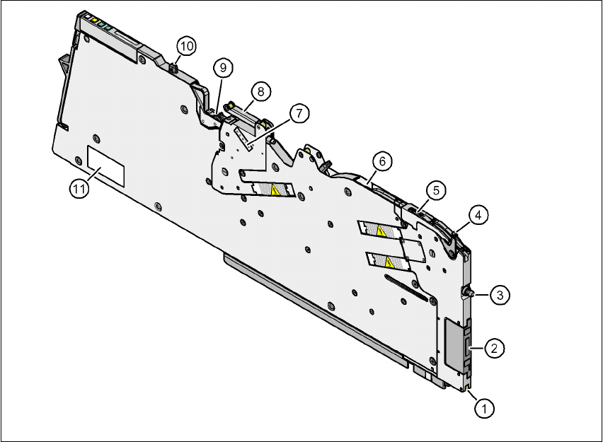
Fig. 6.1 - 1 8 mm X tape feeder module - front view
(1) Locking roller (the locking latch of the component table locks the feeder module in its end po-
sition with the locking roller.)
(2) EDIF (energy and data interface)
(3) "Front" centering pin
(4) Lever for raising the pick-up window in order to thread in and remove the component tape
(5) Pick-up window
(6) Exit from the tape guide channel
(7) Setting the cover foil tension
(8) Cover foil rocker
(9) Cover foil packing wheels
(10) "Back" centering pin
(11) Rating plate
6 Component handling User manual SIPLACE X-Series
6.1 X feeder modules for the component trolley from the SIPLACE X-series Software Version SR.601.xx 11/2005 US Edition
290
6
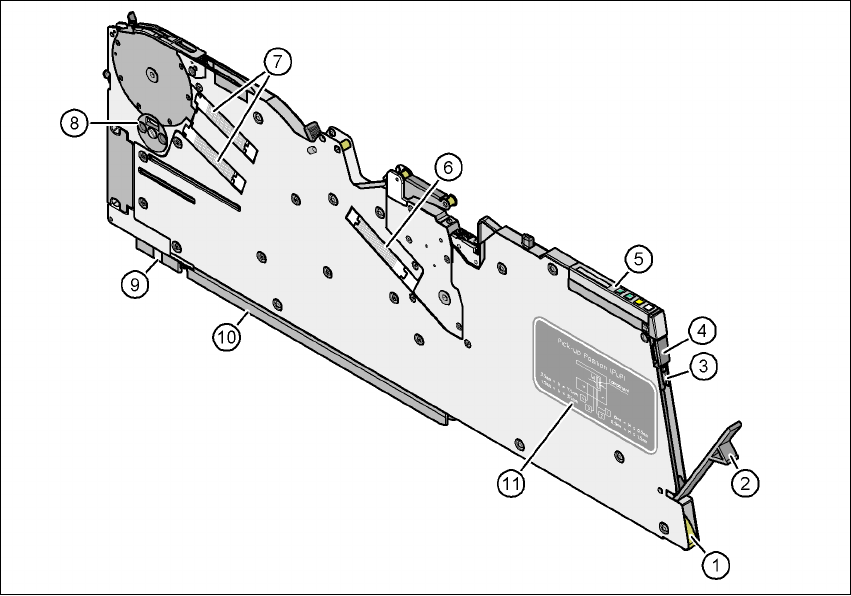
Fig. 6.1 - 2 8 mm X tape feeder module - back view
(1) Entry to the tape guide channel with tape spring
(2) Flap on the cover foil container
(3) Integrated blade for cutting off the cover foil
(4) Removal handle, engaged
(5) Operator panel
(6) Drive motor for the cover foil packing device
(7) Drive motors for the tape conveyor
(8) Rotary valve for removing components
(9) Front slider guide
(10) Back slider guide
(11) Graphical representation of the pick-up position in relation to the component size
User manual SIPLACE X-Series 6 Component handling
Software Version SR.601.xx 11/2005 US Edition 6.1 X feeder modules for the component trolley from the SIPLACE X-series
291
6
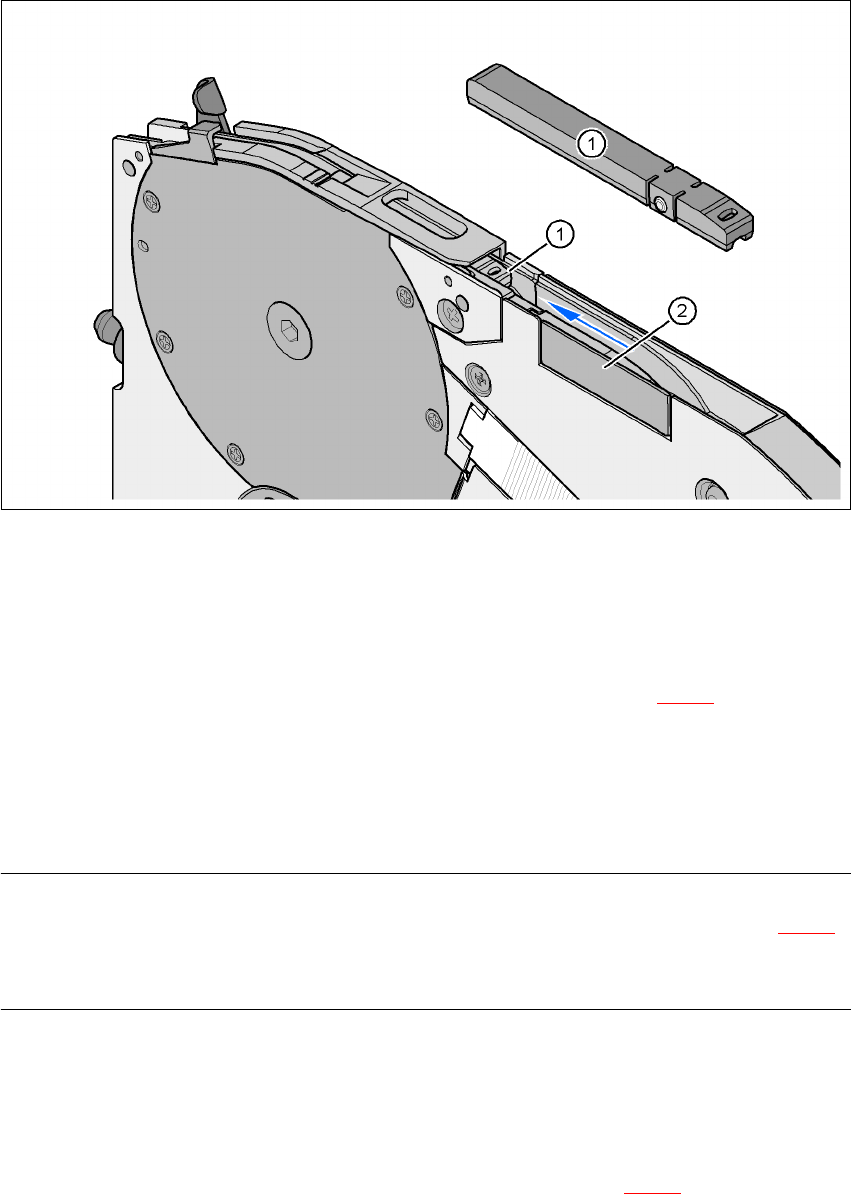
Fig. 6.1 - 3 8 mm X feeder module - tape support and splice sensor
(1) Tape support, removable
(2) Splice sensor installation location
The 8 mm X feeder module is equipped with a tape support (item 1 in Fig. 6.1 - 3
). It can easily
be removed if necessary.
Æ Insert the tang of a watchmaker's screwdriver into the oval opening in the tape support and
pull the tape support out against the direction of travel of the tape.
Æ When you insert the tape support, make sure that it engages in its desired position.
PLEASE NOTE 6
For all components size 0402 and smaller, always insert the tape support (item 1 in Fig. 6.1 - 3
)
into the 8 mm X feeder module. This will give you a constant Z pick up height and will minimize
the time needed to correct the pick up heights.
Splice sensors can be retrofitted to the X tape feeder modules. There are two versions of the sen-
sor:
Splice sensor for 8 mm and 12 mm X tape feeder modules
Splice sensor for 16 mm to 88 mm X tape feeder modules 6
The splice sensor is installed at the position indicated by item 2 in Fig. 6.1 - 3
.