X3_X4_Series machine.pdf - 第391页
User manual SIPLAC E X-Series 7 Station extensions Software Vers ion SR.601.xx 11/ 2005 US Ed ition 7.1 Nozzle changer 391 PLEA SE NOT E Make su re that yo u inser t the magaz ine so th at the c enterin g pins sli de int…
7 Station extensions User manual SIPLACE X-Series
7.1 Nozzle changer Software Version SR.601.xx 11/2005 US Edition
390
7.1.2.8 Changing the magazine
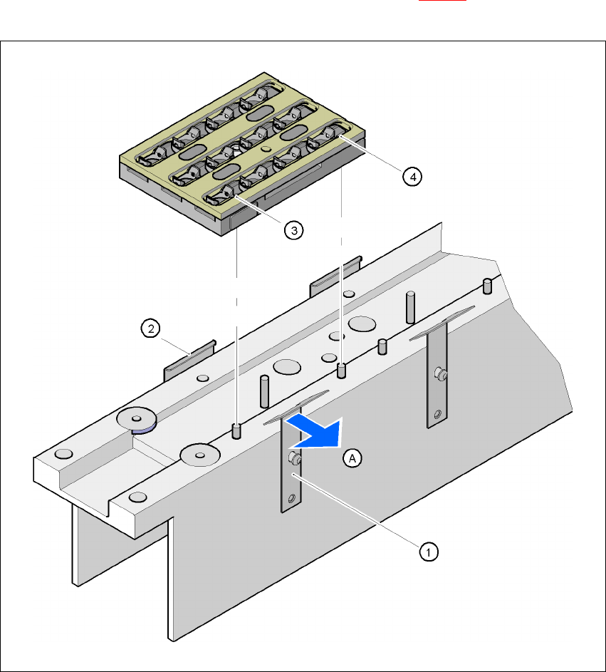
Æ To remove the magazine, push the spring hook (item 1 in Fig. 7.1 - 16) away from the mag-
azine. Lift the magazine out of the carrier.
7
Fig. 7.1 - 16 Changing the magazine
(1) Spring hook
(2) Retaining clamp
(3) Centering hole
(4) Slot
(A) Push the spring hook away from the magazine
User manual SIPLACE X-Series 7 Station extensions
Software Version SR.601.xx 11/2005 US Edition 7.1 Nozzle changer
391
PLEASE NOTE
Make sure that you insert the magazine so that the centering pins slide into the centering hole
(item 3 in Fig. 7.1 - 16) and slot (item 4 in Fig. 7.1 - 16). 7
Æ First place the side of the magazine with the numbered nozzles 1, 2, 3 and 4 on the base.
The retaining clamp (item 2 in Fig. 7.1 - 16
) must slide into the slot in the magazine.
Æ Push the spring hook away from the magazine.
Æ Press the magazine so that it lies flat on the base, then release the spring hook. The spring
hook must latch into place.
7.1.2.9 Position detection
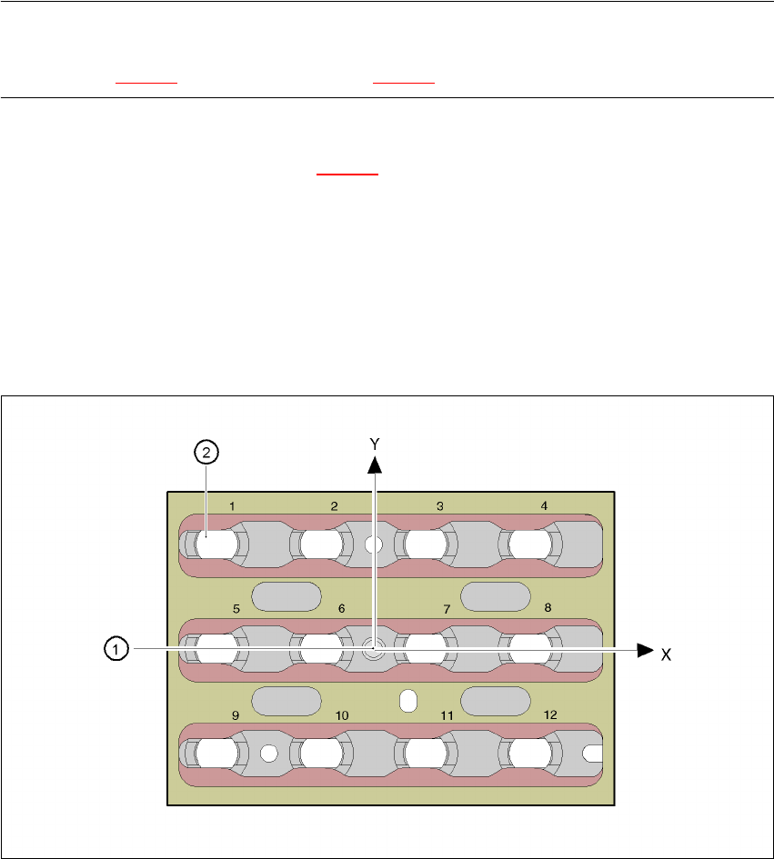
Every magazine of the nozzle changer has a positioning fiducial for position detection.
7
Fig. 7.1 - 17 Nozzle changer - Position detection
(1) Positioning fiducial
(2) Position of the nozzles in the magazine relative to the positioning fiducial
7 Station extensions User manual SIPLACE X-Series
7.1 Nozzle changer Software Version SR.601.xx 11/2005 US Edition
392
7.1.2.10 "Row 2" nozzle changers for the 12-segment Collect&Place head
Item no. 00119663-xx
The "row 2" nozzle changer may be installed at the following locations:
X4 placement machine: Locations 1, 2, 3 and 4 (see Fig. 7.1 - 11
, page 383)
X3 placement machine: Locations 1, 3 and 4 (see Fig. 7.1 - 12
, page 384)
X2 placement machine: Locations 1 and 3 (see Fig. 7.1 - 13
, page 385)
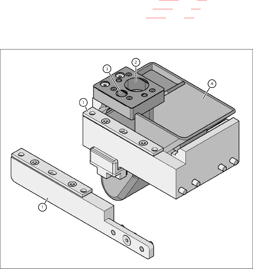
The retrofit package contains an assembly kit and a nozzle take-off device with reject bin, in ad-
dition to the nozzle changer.
7
Fig. 7.1 - 18 Assembly kit for the "row 2" nozzle changer
(1) Assembly kit for the "row 2" nozzle changer
(2) Nozzle take-off device for type 8xx nozzles
(3) Nozzle take-off device for type 9xx nozzles
(4) Nozzle reject bin