X3_X4_Series machine.pdf - 第268页
5 Tasks on the machine User manual SIPLAC E X-Series 5.5 Setting up the X feeder module Software Version SR. 601.xx 11/2005 US Edition 268 5.5 Setting up the X feeder module Settin g up the X f eeder modules is de scribe…
User manual SIPLACE X-Series 5 Tasks on the machine
Software Version SR.601.xx 11/2005 US Edition 5.4 Setting up the feeder modules
267
5
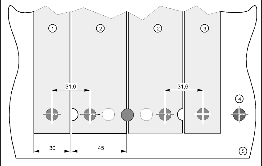
Fig. 5.4 - 9 Inserting 30 or 45 mm wide S feeder modules on the component feeder table
(1) Feeder module, 30 mm wide
(2) Feeder module, 45 mm wide
(3) Feeder module, 30 mm wide
5 Tasks on the machine User manual SIPLACE X-Series
5.5 Setting up the X feeder module Software Version SR.601.xx 11/2005 US Edition
268
5.5 Setting up the X feeder module
Setting up the X feeder modules is described in the job guide.
5.6 LCD and status displays on the X feeder module
The X feeder modules have a multicolor status display (Pos. 6) for signaling the operating statuses
and an LCD display (item 1) to display the texts.
– If the status display lights up green, the feeder module is on standby and is contained in
the current set-up. If the feeder module is not contained in the current set-up, the status
display remains off.
– If the status display lights up orange, it is signaling a warning. The text of the warning
appears on the LCD display.
– If the status display lights up red, a malfunction has occurred. The error message is out-
put on the LCD display.
5
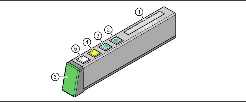
Fig. 5.6 - 1 Buttons, LCD and status displays on the X feeder module
(1) LCD display
(2) FORWARD button
(3) BACK button
(4) FOIL button
(5) SET button
(6) Status display, multicolor
The following tables containing the wording of the LCD display, the color and the mode of the sta-
tus display, its meaning and troubleshooting measures.

User manual SIPLACE X-Series 5 Tasks on the machine
Software Version SR.601.xx 11/2005 US Edition 5.6 LCD and status displays on the X feeder module
269
5.6.1 Warnings
5
5
5.6.2 Error messages and trouble-shooting
5
Text on the
LCD display
Status
display
Meaning Trouble-shooting
Remove Foil Orange The selected function is not
permitted when the cover foil
is tensioned (foil rocker is
pressed down).
If you wish to carry out that function, remove
the foil from the pair of gear wheels and cut
it off to relieve the pressure on the foil rocker.
Text on the
LCD display
Status
display
Meaning Trouble-shooting
none Red,
flashing
Feeder module software not
jumping to the application
Reload the application software
Load feeder module software
Handle --->> Red Feeder module was sig-
naled, but removal handle is
not yet pushed in
Push in the removal handle
Low Voltage Orange 24V supply voltage did not
rise above the switch-on
threshold after switching on
Check the power supply
Low Voltage Red 24V supply voltage rose
above the switch-on thresh-
old after switching on and
was then interrupted
Check the power supply
Feed Timeout
TransTimeout
(Timeout in tape
feeder cycle)
Red Tape feeder cycle did not
end correctly within the spec-
ified time (timeout for the
"Feed" function)
Is the tape reel jammed in the container?
Is there a component jammed in the pick-up
area between component tape and compo-
nent window?
Once the obstacle has been eliminated, use
the arrow keys to restart the conveyor. The
feeder module will move the defective con-
veyor to the end, and then returned to its
position
Foil Torn Red Foil was not tensioned within
the specified time
The foil is probably torn. Insert new foil and
tension
Foil PeelErr Red Foil was not peeled off even
though the tape is moved
The cover foil is probably jammed beneath
the pick-up window and cannot be peeled
off correctly