X3_X4_Series machine.pdf - 第415页
User manual SIPLAC E X-Series 7 Station extensions Software Vers ion SR.601.xx 11/ 2005 US Ed ition 7.4 Multicolor PCB camera, type 24, digital 415 7.4 M ulticolo r PCB camera, type 2 4, di git al 7.4.1 Structure Item no…

7 Station extensions User manual SIPLACE X-Series
7.3 Component camera for the TwinHead, FC camera Software Version SR.601.xx 11/2005 US Edition
414
7.3.1.3 Technical data
7
7
7
7
7.3.2 Safety instructions for the TwinHead component cameras during
a placement head change
WARNING 7
When the placement head is changed from the TwinHead to the Collect&Place head, the Twin-
Head's component cameras (stationary, P&P, type 33, 55 x 45, and type 25, 16 x 16) must be
removed, otherwise the Collect&Place head will collide with the camera housings.
Component dimensions 0.2 x 0.2 mm² up to 16 x 16 mm² for single component measurement
Range of components 0201 to SO, PLCC, QFP, sockets, plugs, BGA, special components,
bare dies, flip-chips, shields
Min. lead pitch 0.25 mm
Min. ball pitch 0.14 mm
Min. ball diameter 0.08 mm
Field of vision 19 x 19 mm²
Method of illumination Front-lighting (6 levels, programable as required)
User manual SIPLACE X-Series 7 Station extensions
Software Version SR.601.xx 11/2005 US Edition 7.4 Multicolor PCB camera, type 24, digital
415
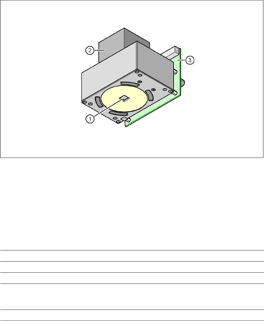
7.4 Multicolor PCB camera, type 24, digital
7.4.1 Structure
Item no. 00119774-xx
7
Fig. 7.4 - 1 Digital multicolor PCB camera, type 24
(1) PCB camera lens and illumination
(2) Camera amplifier
(3) Illumination control
7
7
7.4.2 Technical data
7
Field of vision 5.7 x 5.7 mm²
Distance from the focus plane 28 mm
Method of illumination Front-lighting (5 levels, programable as required)
Fiducial size 0.3 mm to 2.5 mm edge length for a PCB feeder tolerance
of ± 1.0 mm
to 3.0 mm edge length for a PCB feeder tolerance of < 1.0 mm
Bad fiducial size 0.3 mm to 3.0 mm edge length

7 Station extensions User manual SIPLACE X-Series
7.4 Multicolor PCB camera, type 24, digital Software Version SR.601.xx 11/2005 US Edition
416
7.4.3 Type of illumination
The following types of illumination can be selected on the multicolor PCB camera:
– White lighting
This type of illumination is used for standard PCBs with tinned fiducials.
– Blue oblique lighting
In most cases, this can be used to greatly improve the contrast with bright fiducials on a light
base material, such as ceramic or CEM. Fiducials covered with solder resist can also be de-
tected better on a light background.
– Infrared lighting
This type of illumination is particularly useful for fiducials that are covered with solder resist
or for fiducials on flex materials. It is also sometimes possible to improve detection of silver/
platinum fiducials on ceramic. This should be tested by carrying out a test centering or place-
ment run.
7.4.4 Fiducial and ink spot criteria
The fiducials and ink spot criteria are described in sections 3.11.5.3 and 3.11.5.4, page 162.