X3_X4_Series machine.pdf - 第307页
User manual SIPLAC E X-Series 6 Component han dling Software Vers ion SR.601.xx 11/2005 US Edition 6.2 SIPLAC E X-series c omponent trolley 307 6.2.1 S tructure of t he compone nt trolley SIPLACE X-series The com ponent …
6 Component handling User manual SIPLACE X-Series
6.2 SIPLACE X-series component trolley Software Version SR.601.xx 11/2005 US Edition
306
The component changeover tables are stand-alone modules that can be set up with feeders at an
external set-up area. This means that the production process only has to be interrupted briefly in
order to change the component trolley.
6
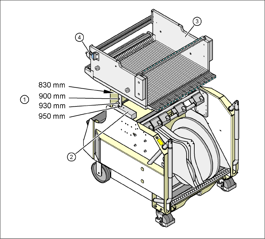
Fig. 6.2 - 2 Component trolley, SIPLACE X-series with a PCB conveyor height of 950 mm
6
(1) Holes for the PCB conveyor heights 900, 930 and 950 mm in the guide columns. For the
830 mm conveyor height, the component table lies on the block (2).
(2) Supporting block
(3) Component feeder table
(4) Contact for switching the safety switch in the component trolley docking unit
User manual SIPLACE X-Series 6 Component handling
Software Version SR.601.xx 11/2005 US Edition 6.2 SIPLACE X-series component trolley
307
6.2.1 Structure of the component trolley SIPLACE X-series
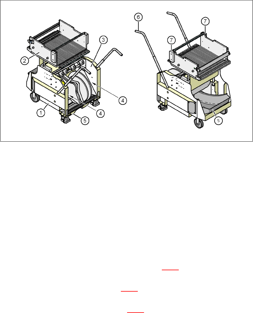
The component trolley essentially consists of the chassis, the component table for holding the
feeder modules, the tape reel container and the waste container.
6
Fig. 6.2 - 3 Component trolley, SIPLACE X-series, front and back view
(1) Chassis
(2) Component feeder table
(3) Tape container
(4) Slot for holding set-up lists
(5) Waste tape container
(6) Handle
(7) Hand guard
6
6
Description of the modules 6
In the standard version, the tape reel container (item 3 in Fig. 6.2 - 3) holds tape reels up to 17"
(432 mm).
There are two 5 mm wide gaps (item 4 in Fig. 6.2 - 3
) on the left and right between the tape con-
tainer and the component trolley for holding set-up lists.
The pull-out waste tape container (item 5 in Fig. 6.2 - 3
) can be found beneath the chassis. The
cut waste tape travel down a chute into the waste container, which must be emptied as it fills up.
6 Component handling User manual SIPLACE X-Series
6.2 SIPLACE X-series component trolley Software Version SR.601.xx 11/2005 US Edition
308
The handles (item 6 in Fig. 6.2 - 3) can be folded up or down.
NOTE ON OPERATIONAL SAFETY 6
All component trolleys or matrix tray changers must be docked on the machine in order to oper-
ate it. Free locations must also be filled with dummy feeder modules.
6.2.2 Technical data for the SIPLACE X-series component trolley
6
6
Length x width 727 x 592 mm²
752 x 592 mm² with waste container
Height of the component table 819.5 mm for 830 mm PCB transport height
889.5 mm for 900 mm PCB transport height
919.5 mm for 930 mm PCB transport height
939.5 mm for 950 mm PCB transport height
PCB transport height 830 mm ± 15 mm (standard)
900 mm ± 15 mm (SMEMA)
930 mm ± 15 mm (SMEMA)
950 mm ± 15 mm (SMEMA)
Height of the folded up handles 969 mm
Number of locations 40 (8 mm X tape feeder module)
Weight
Without feeder modules
With feeder module at all locations
Approx. 80.4 kg
Approx. 139.6 kg
Reel diameter
Standard
Maximum
Up to 432 mm (17")
483 mm (19")