X3_X4_Series machine.pdf - 第306页
6 Component handling User manual SIPLACE X-Series 6.2 SIPLACE X -series component trolley Software Version SR.601.x x 11/2005 US Edition 306 The comp onent chan geover tables are stand-alon e modul es that can b e set up…
User manual SIPLACE X-Series 6 Component handling
Software Version SR.601.xx 11/2005 US Edition 6.2 SIPLACE X-series component trolley
305
6.2 SIPLACE X-series component trolley
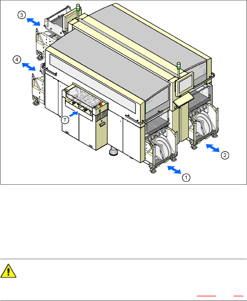
Up to four SIPLACE X-series component trolleys can be docked into the machines from the
SIPLACE X-series. The locations are numbered as shown in the diagram below.
6
Fig. 6.2 - 1 Component trolley locations, SIPLACE X-series
(1) Location 1
(2) Location 2
(3) Location 3
(4) Location 4
(T) PCB direction of travel
CAUTION 6
The component trolleys from the SIPLACE X-series may only be docked into locations at which
the component trolley docking unit for the SIPLACE X-series is installed (Fig. 5.10 - 3, page 278).
6 Component handling User manual SIPLACE X-Series
6.2 SIPLACE X-series component trolley Software Version SR.601.xx 11/2005 US Edition
306
The component changeover tables are stand-alone modules that can be set up with feeders at an
external set-up area. This means that the production process only has to be interrupted briefly in
order to change the component trolley.
6
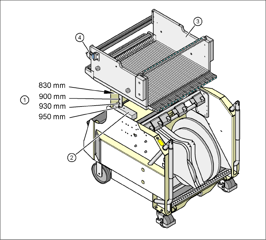
Fig. 6.2 - 2 Component trolley, SIPLACE X-series with a PCB conveyor height of 950 mm
6
(1) Holes for the PCB conveyor heights 900, 930 and 950 mm in the guide columns. For the
830 mm conveyor height, the component table lies on the block (2).
(2) Supporting block
(3) Component feeder table
(4) Contact for switching the safety switch in the component trolley docking unit
User manual SIPLACE X-Series 6 Component handling
Software Version SR.601.xx 11/2005 US Edition 6.2 SIPLACE X-series component trolley
307
6.2.1 Structure of the component trolley SIPLACE X-series
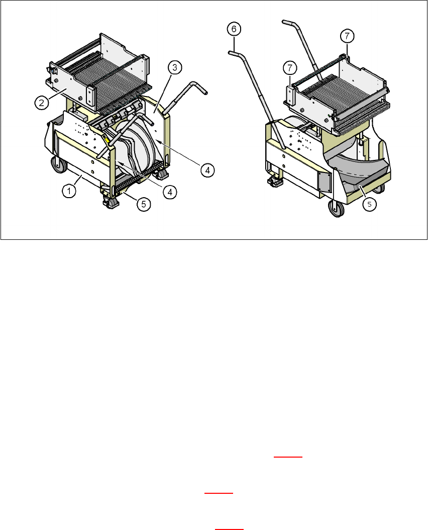
The component trolley essentially consists of the chassis, the component table for holding the
feeder modules, the tape reel container and the waste container.
6
Fig. 6.2 - 3 Component trolley, SIPLACE X-series, front and back view
(1) Chassis
(2) Component feeder table
(3) Tape container
(4) Slot for holding set-up lists
(5) Waste tape container
(6) Handle
(7) Hand guard
6
6
Description of the modules 6
In the standard version, the tape reel container (item 3 in Fig. 6.2 - 3) holds tape reels up to 17"
(432 mm).
There are two 5 mm wide gaps (item 4 in Fig. 6.2 - 3
) on the left and right between the tape con-
tainer and the component trolley for holding set-up lists.
The pull-out waste tape container (item 5 in Fig. 6.2 - 3
) can be found beneath the chassis. The
cut waste tape travel down a chute into the waste container, which must be emptied as it fills up.