X3_X4_Series machine.pdf - 第304页
6 Component handling User manual SIPLACE X-Series 6.1 X feeder modules for the c omponent trolley fro m the SIPLACE X-series Software Version SR. 601.xx 11/2005 US Edition 304 W ARNING 6 All loc ations m ust be eq uipped…

User manual SIPLACE X-Series 6 Component handling
Software Version SR.601.xx 11/2005 US Edition 6.1 X feeder modules for the component trolley from the SIPLACE X-series
303
6.1.3.1 Technical data
*) X feeder modules can be positioned at the remaining 8 locations. If locking and retaining rails
are used, however, the fixing lever projecting at the side reduces the available locations to 6.
6.1.3.2 Number of waffle-pack trays per location and machine
6.1.3.3 Using the waffle-pack tray holder on the X-series component trolley
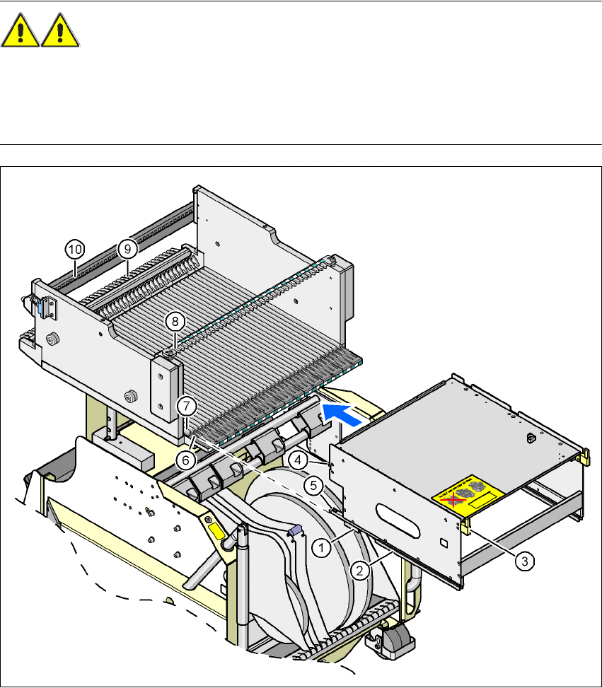
Æ Place the two front slider guides (item 1 in Fig. 6.1 - 15, page 304) of the holder on the inser-
tion aid (item 6).
Æ Push the holder forward along the guide profiles (item 7). The holder will slide with its front
(item 1) and rear slider guides (item 2) on the guide profiles.
Æ Carefully push the holder further until the two "front" centering pins (item 4) disappear into the
centering holes (item 10).
Æ Watch the two "rear" centering pins (item 3) on the holder. They must slide easily into the re-
cesses (item 8) on the centering bar.
Æ When the holder is at the stop position, the locking tabs (item 9) engage on the locking rollers
(item 5) on the holder.
The waffle-pack tray holder can be locked and released via the user interface. It is therefore not
possible to change the holder while placement is in progress.
Dimensions L x W x H 429 mm x 376 mm x 200 mm
Location filled on the component table 32 locations
*)
Positioning option on the X-series machines Locations 2 and 4
Software
Station software SR.601.xx or later
Programming system SIPLACE Pro 3.0 or later
Range of placement heads TwinHead, C&P6, C&P12
Placement machine Location 2 Location 4
X4 1 1
X3 2 1
X2 2 2
6 Component handling User manual SIPLACE X-Series
6.1 X feeder modules for the component trolley from the SIPLACE X-series Software Version SR.601.xx 11/2005 US Edition
304
WARNING 6
All locations must be equipped with feeder modules in order to guarantee operational reliability. If
there are not enough feeder modules available, unassigned locations should be fitted with a
hand guard (dummy feeder module). When a waffle-pack tray is set up, the remaining locations
have to be protected again with a hand guard.
6
Fig. 6.1 - 15 Inserting a waffle-pack tray holder for the component trolley from the SIPLACE X-series
(1) Front slider guide (6) Insertion aid
(2) Back slider guide (7) Slide bar (omega profile)
(3) "Back" centering pin (8) Recess in the centering bar for holding the
"back" centering pin
(4) "Front" centering pin (9) Locking latches
(5) Locking roller (10) Centering holes on the component table for
holding the "front" centering pin
User manual SIPLACE X-Series 6 Component handling
Software Version SR.601.xx 11/2005 US Edition 6.2 SIPLACE X-series component trolley
305
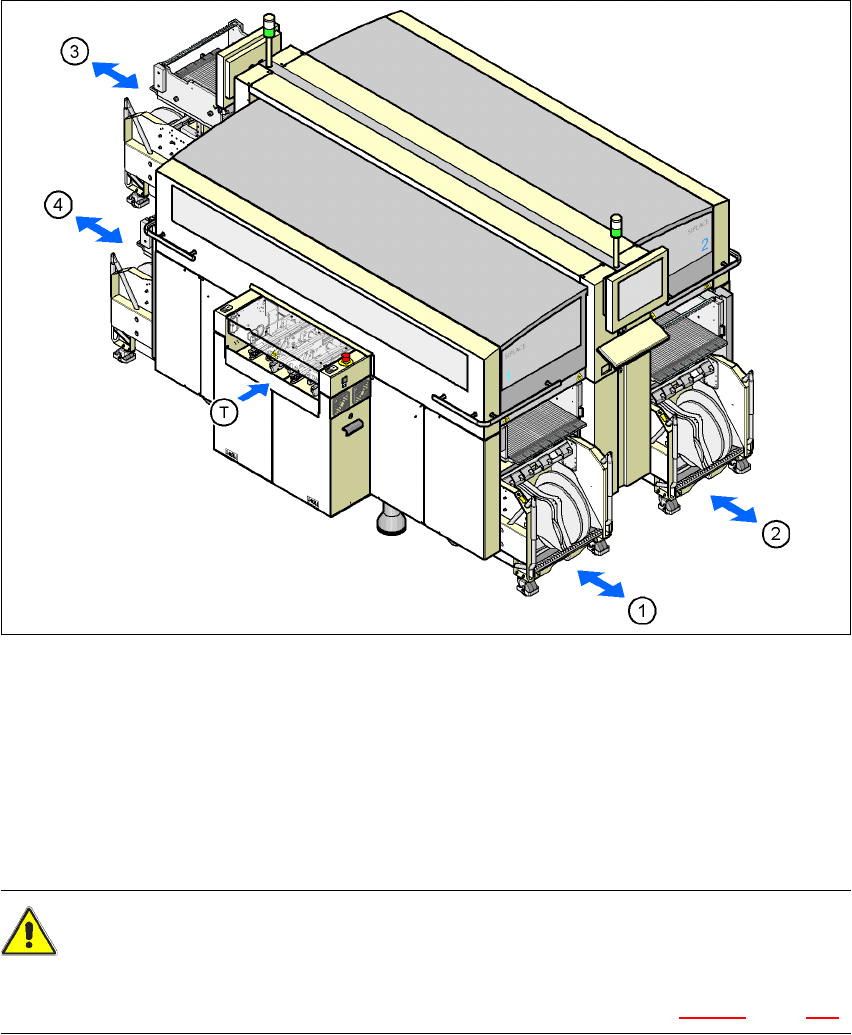
6.2 SIPLACE X-series component trolley
Up to four SIPLACE X-series component trolleys can be docked into the machines from the
SIPLACE X-series. The locations are numbered as shown in the diagram below.
6
Fig. 6.2 - 1 Component trolley locations, SIPLACE X-series
(1) Location 1
(2) Location 2
(3) Location 3
(4) Location 4
(T) PCB direction of travel
CAUTION 6
The component trolleys from the SIPLACE X-series may only be docked into locations at which
the component trolley docking unit for the SIPLACE X-series is installed (Fig. 5.10 - 3, page 278).