X3_X4_Series machine.pdf - 第267页
User manual SIPLAC E X-Series 5 Tasks on the machine Software Vers ion SR.601.xx 11/ 2005 US Ed ition 5.4 Setting up the feeder m odules 267 5 Fig. 5.4 - 9 Inserting 30 or 45 mm wide S feeder modules on the component fee…
5 Tasks on the machine User manual SIPLACE X-Series
5.4 Setting up the feeder modules Software Version SR.601.xx 11/2005 US Edition
266
5.4.5.1 Preparing the component feeder table (SIPLACE HF) and S feeder modules
for set-up
Æ Clean the contact surface for the feeder module.
Æ Clean the contact surface on the component feeder table.
Æ Remove loose components from the component feeder table with a brush or use a vacuum
cleaner with appropriate nozzle.
CAUTION 5
Avoid removing components from the component table with your fingers. You may hurt your-
self with tiny splinters of metal.
5.4.6 Inserting the S feeder module
Æ First place the front of the feeder module (item 1 in Fig. 5.4 - 8), i.e. the side with the slotted
foot, onto the component feeder table (item 4 in Fig. 5.4 - 8
) so that the centering pin (item 2)
on the component feeder table slides into the slot in the feeder module foot.
Æ Then lower the back of the feeder module until the centering ball (item 3 in Fig. 5.4 - 8) dis-
appears into the hole in the feeder module.
Æ Make sure that the feeder modules are placed correctly on the component feeder table to suit
their width (see Fig. 5.4 - 9
).
Æ Check that the feeder module is firmly seated on the component feeder table.
Æ Connect the feeder module plug (item 5 in Fig. 5.4 - 8) to the socket beneath the location.
PLEASE NOTE 5
When you connect the feeder module, make sure that you use the right socket for the location
since the feeder module receives the control pulse via this socket. The feeder module may
not work correctly if it is not connected to the right socket. The user manual for the feeder
modules used will contain detailed information on the assignment of plugs to sockets.
User manual SIPLACE X-Series 5 Tasks on the machine
Software Version SR.601.xx 11/2005 US Edition 5.4 Setting up the feeder modules
267
5
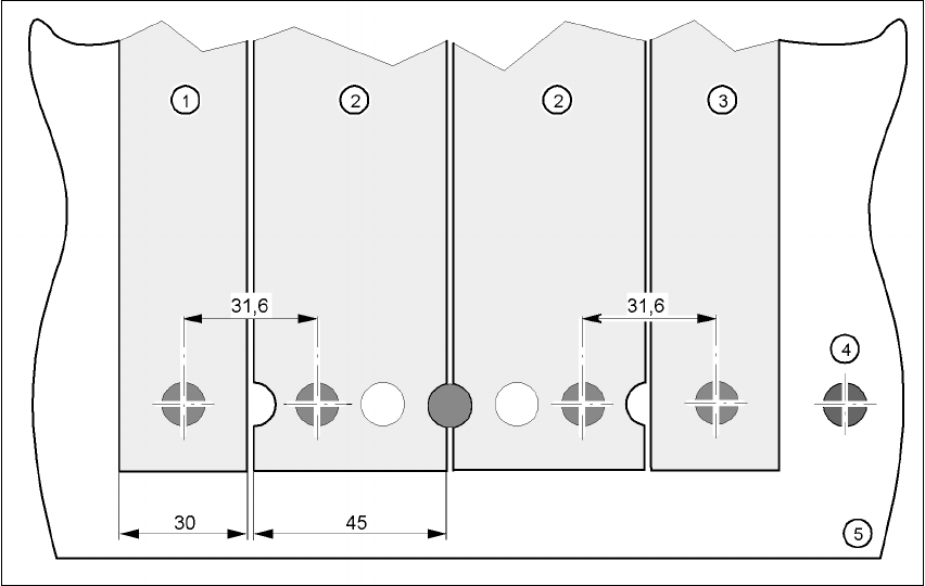
Fig. 5.4 - 9 Inserting 30 or 45 mm wide S feeder modules on the component feeder table
(1) Feeder module, 30 mm wide
(2) Feeder module, 45 mm wide
(3) Feeder module, 30 mm wide
5 Tasks on the machine User manual SIPLACE X-Series
5.5 Setting up the X feeder module Software Version SR.601.xx 11/2005 US Edition
268
5.5 Setting up the X feeder module
Setting up the X feeder modules is described in the job guide.
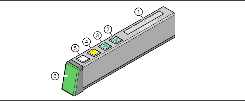
5.6 LCD and status displays on the X feeder module
The X feeder modules have a multicolor status display (Pos. 6) for signaling the operating statuses
and an LCD display (item 1) to display the texts.
– If the status display lights up green, the feeder module is on standby and is contained in
the current set-up. If the feeder module is not contained in the current set-up, the status
display remains off.
– If the status display lights up orange, it is signaling a warning. The text of the warning
appears on the LCD display.
– If the status display lights up red, a malfunction has occurred. The error message is out-
put on the LCD display.
5
Fig. 5.6 - 1 Buttons, LCD and status displays on the X feeder module
(1) LCD display
(2) FORWARD button
(3) BACK button
(4) FOIL button
(5) SET button
(6) Status display, multicolor
The following tables containing the wording of the LCD display, the color and the mode of the sta-
tus display, its meaning and troubleshooting measures.