X3_X4_Series machine.pdf - 第124页
3 Technical data User manual SIPLACE X-Series 3.7 Placement heads Software Version SR.601.xx 11/2005 US Edition 124 Fig. 3.7 - 6 Description of the functions (1) Com ponent pic k-up p osition, placemen t posi tion, reje …

User manual SIPLACE X-Series 3 Technical data
Software Version SR.601.xx 11/2005 US Edition 3.7 Placement heads
123
– The package form is also checked and the component is not placed if the geometric data
thus determined differs from the programmed data.
– A digital component camera on the placement head determines the precise position of
each component at the nozzle. The 20-segment Collect&Place head camera can opti-
cally center components from 0.2 x 0.2 mm² to 6 x 6 mm². Any deviations from the re-
quired pick-up position are corrected before placement takes place. When a component
is picked up, the average of the deviations for the last 10 placement operations is taken
into account, thus increasing the pick-up accuracy.
3.7.2.3 Description of the functions
The 20-segment Collect&Place head has three axes - the DR or star axis, the Z axis and the
DP axis.
Star axis (item 3 in Fig. 3.7 - 5) 3
The star rotates about the star axis with its 20 DP drives. This is tilted away from the vertical. A
three-phase servomotor with position control is used as the drive motor. An optoelectronic en-
coder returns information about the angle of rotation at the axis card. The actual position values
are analyzed on the axis card. The position control on the axis card provides the current and volt-
age setpoint values for the servo amplifier used to operate the star motor. On each DP drive there
is a nozzle that sucks up the component during the pick-up process. The star transports the picked
up component from the pick-up/placement position (item 1 in Fig. 3.7 - 6
) to the optical centering
position (item 11 in Fig. 3.7 - 6
) and onward for placement to the pick-up/placement position. On
the way to the pick-up/placement position, the DP drive rotates the component into the required
placement position.
Z axis (item 6 in Fig. 3.7 - 4) 3
The Z axis performs a vertical movement. A three-phase linear motor is used as the drive. An op-
toelectronic encoder is used to measure positions. A scanner scans the positioning fiducials on a
tape measure and thus returns the position signals to the axis card.
The Z motor is operated with position control. The actual position values are analyzed on the axis
card. The position control on the axis card provides the current and voltage setpoint values for the
servo amplifier used to operate the star motor.
3 Technical data User manual SIPLACE X-Series
3.7 Placement heads Software Version SR.601.xx 11/2005 US Edition
124
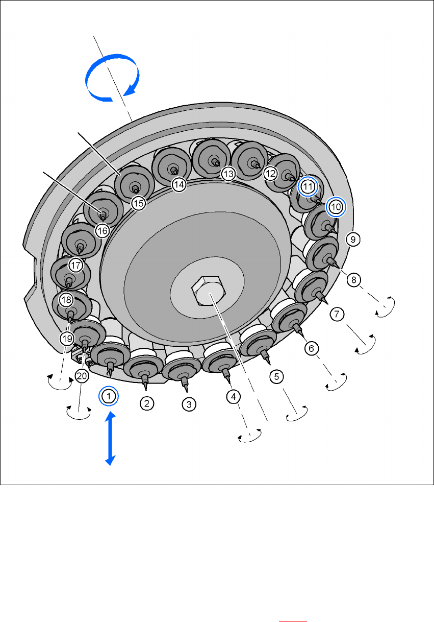
Fig. 3.7 - 6 Description of the functions
(1) Component pick-up position, placement position, reject position, component check with
component sensor
(10) Vacuum check of the nozzle in the holding circuit, with or without component
(11) Position for optical centering of the components
Every DP drive that is in the bottom star position (item 1 in Fig. 3.7 - 6
) is raised or lowered by this
axis, thus picking up the components from the feeder modules and setting them down on the PCB.
Star rotation
Star axis
DP drive (segment)
Nozzle
Z axis
Check pick up, place or
reject
component with compo-
nent sensor
DP axis
Each sleeve can be
rotated individually.
Component
camera for optical
centering
Nozzle vacuum
check in the
holding circuit

User manual SIPLACE X-Series 3 Technical data
Software Version SR.601.xx 11/2005 US Edition 3.7 Placement heads
125
To detect the set-down height, a "Z axis down" sensor is attached at the placement position. This
detects a relative movement between nozzle and segment. When the Z axis springs into position,
this returns a signal - the sensor stop signal - to the axis card that the precontrol uses to correct
the position control. A pneumatic return system was implemented to avoid the risk of a head crash
when the power is switched off due to the segment being lowered with the sleeve. This keeps the
segment securely in the top position when the power is off. Regardless of this pneumatic return
system (item 5 in Fig. 3.7 - 4
), the control for the Z axis is designed so that, in the event of a power
failure, the placement machine still has sufficient residual energy stored in the servo amplifier to
raise the Z axis into the top position. A "Powerfail" signal in the machine activates the axis card
and the servo amplifier to move the Z axis into the top position.
The Z axis is an "intelligent axis". It "notes" the pick-up height of each feeder module track and the
placement height for each component. The placement process can thus be speeded up, while re-
taining the programmed set-down force.
DP axis (item 1 in Fig. 3.7 - 4) 3
The DP axis turns the component into the desired placement position before centering (item 11 in
Fig. 3.7 - 6
). While the component camera is recording the image, the component must be abso-
lutely stationary, i.e. there must be no control movements of the DP drive. Once the correction
values have been determined, the DP drive turns the component into the definitive placement po-
sition.
Every DP drive has its own DP motor, i.e. the nozzles can be rotated independently of one an-
other.
The DP motor is position-controlled. Position encoders determine the actual values for the axis
motions at the axis card. The actual values are analyzed on the axis card. The position control on
the axis card provides the current and voltage setpoint values for the servo amplifier used to op-
erate the DP motors.
Vacuum system 3
The vacuum system consists of two vacuum circuits - the pick-up/placement circuit and the hold-
ing circuit. The two circuits are coupled together at the "Pick-up, place, eject" star position (item 1
in Fig. 3.7 - 6
).
The vacuum for the pick-up/placement circuit is generated by a vacuum nozzle. The values for the
current pressure and vacuum statuses are sent to the control circuit by an integral pressure/vac-
uum sensor. This control circuit allows the circuit to switch quickly and smoothly between vacuum
and air kiss. Rapid evacuation of the circuit, in turn, leads to reliable component suction, and thus
increases pick-up reliability. Rapid build-up of an air pulse for setting down the component on the
PCB, in turn, increases the placement speed.
In the holding circuit, each segment is supplied with a vacuum by a separate vacuum nozzle. The
segments are disconnected from one another, and so cannot affect one another. Even if the wrong