X3_X4_Series machine.pdf - 第169页
User manual SIPLAC E X-Series 3 Technical data Software Version SR.601.xx 11/2005 US Edition 3. 13 Flexible dual PCB conveyor 169 3.13.5 Defining the conv eyor tracks The right c onveyor tr ack (vie wed in the tr ansport…
3 Technical data User manual SIPLACE X-Series
3.13 Flexible dual PCB conveyor Software Version SR.601.xx 11/2005 US Edition
168
3.13.3 Description of the functions
The flexible dual conveyor has two conveyor tracks that are electrically and mechanically inde-
pendent of one another. The functions are the same as for the single conveyor (see Section
3.12.3
, page 164.
3.13.4 "Flexible dual conveyor" performance feature
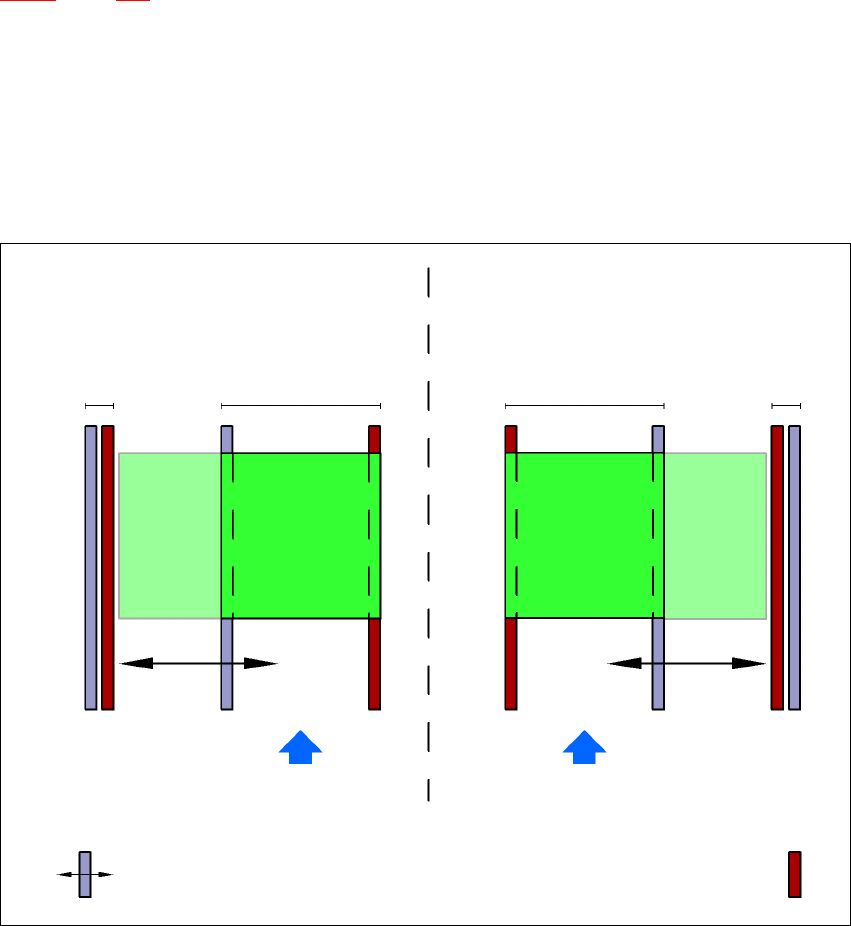
The "flexible dual conveyor" performance feature allows the conveyor track to be widened beyond
the standard width of 216 mm. Over-wide PCBs can then be processed in a machine with a dual
conveyor. The side walls of the second conveyor track are moved fully together, which deactivates
the conveyor track at the same time.
3
Fig. 3.13 - 2 Flexible dual conveyor in Single conveyor mode
3
3
Dual conveyor with widened conveyor track 2
(stationary conveyor side wall on left)
Conveyor track
2 deactivated
Conveyor track 1 Conveyor track 2 Conveyor track 1
deactivated
PCB transport direction PCB transport direction
Stationary conveyor side wall
Dual conveyor with widened conveyor track 1
(stationary conveyor side wall on right)
Movable conveyor side wall

User manual SIPLACE X-Series 3 Technical data
Software Version SR.601.xx 11/2005 US Edition 3.13 Flexible dual PCB conveyor
169
3.13.5 Defining the conveyor tracks
The right conveyor track (viewed in the transport direction) is designated "Conveyor 1" and the left
as "Conveyor 2" (see Fig. 3.13 - 3
, page 170).
3.13.6 Definition of the conveyor track width
3.13.6.1 Standard width
The standard width of the conveyor track is the maximum conveyor width defined by the desired
position of the stationary conveyor side. It is no more than 216 mm per track.
3.13.6.2 Overwide conveyor track
The conveyor track can be widened to 250 mm maximum by moving the stationary conveyor side
wall out of its normal position.
3.13.6.3 Dual conveyor in Single conveyor mode
The dual conveyor can be configured online to create a single conveyor. To do this, one conveyor
track is moved fully together and deactivated (see Fig. 3.13 - 2
, page 168). This gives a conveyor
track width of up to 450 mm.
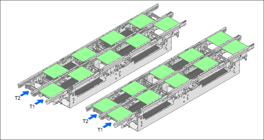
3.13.7 Transport modes
The flexible dual conveyor can be used in two modes:
– Synchronous transport mode
– Asynchronous transport mode
3.13.7.1 Asynchronous transport mode
Description 3
In asynchronous mode, only one PCB in a transport track is processed. At the same time, another
PCB in the second transport track is moved into the placement position. This saves the full con-
veying time of one PCB, thus considerably increasing performance, particularly for PCBs with a
short cycle time.
Function 3
Once the machine has received the job data (panel, set-up), the PCBs on the feeding belts are
continuously transported to the available processing belt (provided that the processing belt is free)
throughout the placement operation. The placement sequence starts as soon as a PCB has
moved onto the processing belt. The PCBs are processed one after another.
3 Technical data User manual SIPLACE X-Series
3.13 Flexible dual PCB conveyor Software Version SR.601.xx 11/2005 US Edition
170
If the placement sequence is interrupted, the conveyor interface will be disabled and the PCBs
currently on the processing belts will be completed.
The conveyor interface is disabled or enabled simultaneously for both transport tracks.
3
Fig. 3.13 - 3 Transport modes
3.13.7.2 Synchronous transport mode
Description 3
In synchronous mode, two PCBs of the same size are moved into the placement position at the
same time. They must be processed as a common panel.
In this way, the top and bottom of a PCB can be processed on a single line, and the time required
to transport the PCB is shorter since two PCBs are always transported at the same time. It also
ensures better utilization of the nozzle configuration.
Function 3
PCBs on conveyor tracks 1 and 2 are moved synchronously onto the conveyor sections (i.e. the
conveyors are controlled synchronously, but independently of one another). The components to
be placed on conveyor tracks 1 and 2 must be organized into a panel via two subpanels. (See the
SIPLACE Pro user manual).
If only one conveyor track (or center conveyor) is full when the placement sequence starts, the
subpanel on this section will be identified as “not for placement”.
Synchronous
transport mode
Asynchronous
transport mode