X3_X4_Series machine.pdf - 第157页
User manual SIPLAC E X-Series 3 Technical data Software Version SR.601.xx 11/2005 US Edition 3.11 Vision cameras 157 3.1 1.1 C&P component camera, type 23, 6 x 6, digit al 3.1 1.1. 1 Structur e 3 Fig. 3.1 1 - 2 C&…

3 Technical data User manual SIPLACE X-Series
3.11 Vision cameras Software Version SR.601.xx 11/2005 US Edition
156
WARNING
RISK OF HEAD CRASH 3
When the placement head is changed from the TwinHead to the Collect&Place head, the Twin-
Head's stationary component vision camera, P&P (type 33) 55 x 45, and stationary P&P compo-
nent vision camera (type 25) 16 x 16 digital must be removed, otherwise the Collect&Place head
will collide with the camera housings.
The
component vision module
is used to determine:
– the precise position of the components at the nozzle and
– the geometry of the package form.
The
PCB vision module
uses fiducials on the PCBs to determine:
– the position of the PCB,
– its rotation angle
– and the PCB skew.
The PCB cameras are fixed to the bottom of the gantries. They use fiducials on the
feeder mod-
ules
to determine the exact pick-up position of components, which is particularly important for
small components.
User manual SIPLACE X-Series 3 Technical data
Software Version SR.601.xx 11/2005 US Edition 3.11 Vision cameras
157
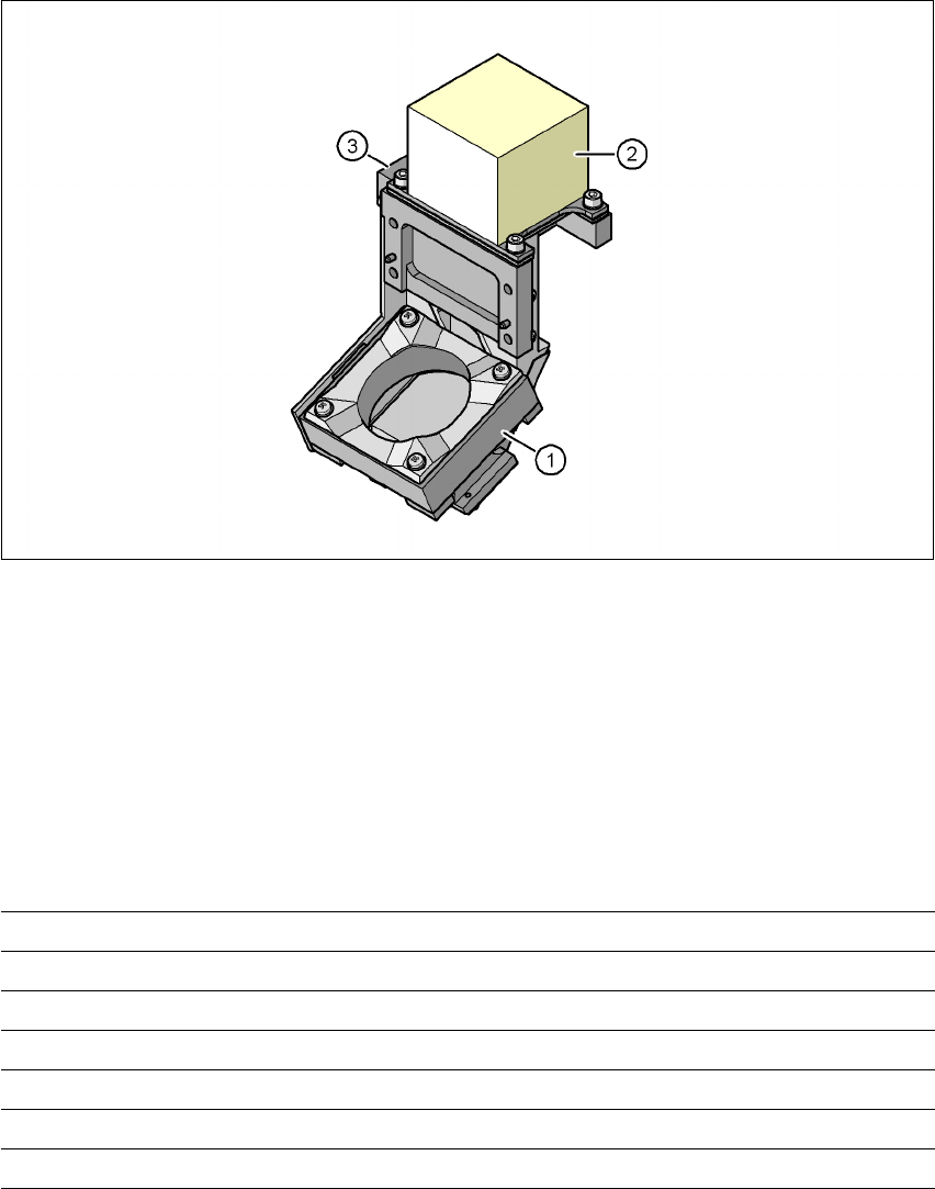
3.11.1 C&P component camera, type 23, 6 x 6, digital
3.11.1.1 Structure
3
Fig. 3.11 - 2 C&P component camera, type 23, 6 x 6, digital
3
(1) Component camera lens and illumination
(2) Camera amplifier
(3) Illumination control
3.11.1.2 Technical data
3
Component dimensions 0.2 x 0.2 mm² to 6 x 6 mm²
Range of components 01005 to 6 x 6 mm²
Min. lead pitch 0.3 mm
Min. ball pitch 0.4 mm
Min. ball diameter 0.2 mm
Field of vision 8 x 8 mm²
Method of illumination Front-lighting (5 levels, programable as required)
3 Technical data User manual SIPLACE X-Series
3.11 Vision cameras Software Version SR.601.xx 11/2005 US Edition
158
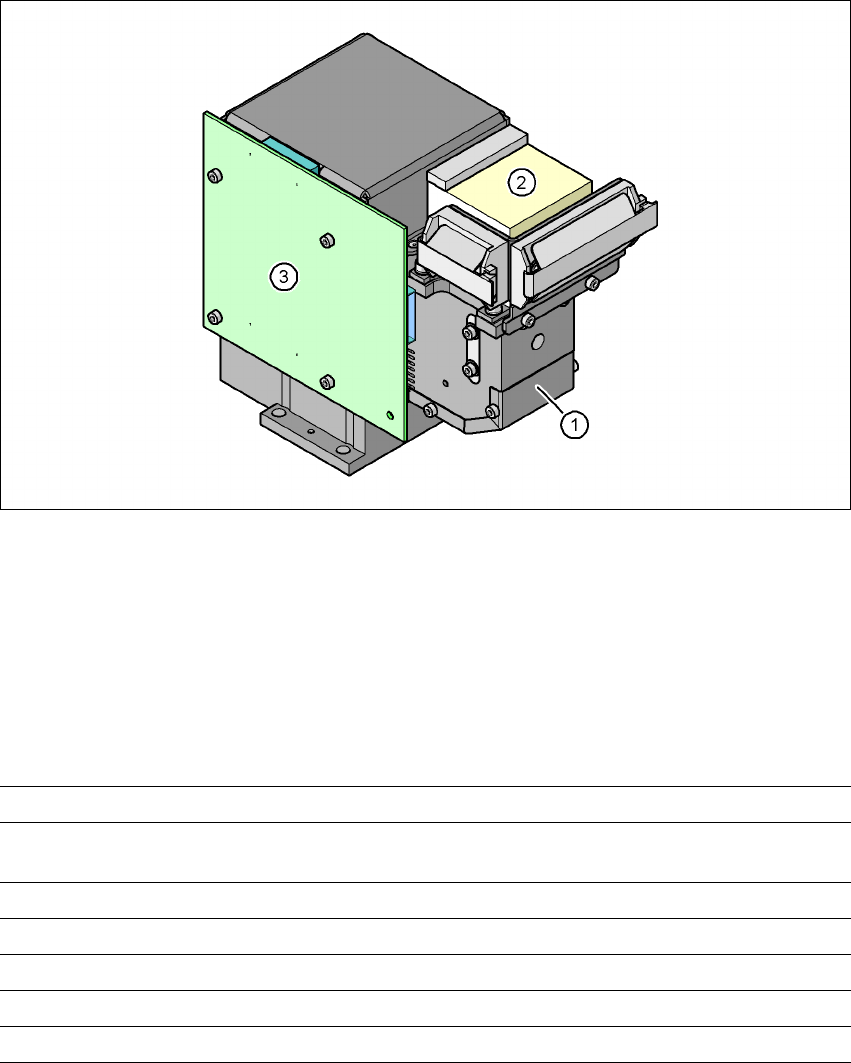
3.11.2 C&P component camera, type 28, 18 x 18, digital
3.11.2.1 Structure
3
Fig. 3.11 - 3 C&P component camera, type 28, 18 x 18, digital
3
(1) Component camera lens and illumination
(2) Camera amplifier
(3) Illumination control
3.11.2.2 Technical data
3
Component dimensions 0.5 x 0.5 mm² to 18.7 x 18.7 mm²
Range of components 0402 to PLCC44 incl. BGA, µBGA, flip-chip, TSOP, QFP,
SO to SO32, DRAM
Min. lead pitch 0.5 mm
Min. ball pitch 0.45 mm
Min. ball diameter 0.25 mm
Field of vision 24.5 x 24.5 mm²
Method of illumination Front-lighting (5 levels, programable as required)