X3_X4_Series machine.pdf - 第121页
User manual SIPLAC E X-Series 3 Technical data Software Vers ion SR.601.xx 11/ 2005 US Ed ition 3.7 Placem ent heads 121 3 Fig. 3.7 - 5 20-segment Collect&Place head - F unction groups, part 2 (1) C&P component c…
3 Technical data User manual SIPLACE X-Series
3.7 Placement heads Software Version SR.601.xx 11/2005 US Edition
120
3.7.2 20-nozzle Collect&Place head for very high-speed placement
3
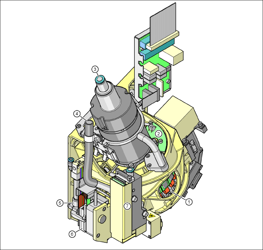
Fig. 3.7 - 4 20-segment Collect&Place head - Function groups, part 1
(1) DP drive, 20 drives
(2) "Vacuum sensor holding circuit" board
(3) Compressed air connection for 20 Venturi nozzles in the pick-up/placement and holding
circuit
(4) Line for the exhaust air from the pressure control valve (7)
(5) Return cylinder
(6) Z motor (linear motor)
(7) Pressure control valve
User manual SIPLACE X-Series 3 Technical data
Software Version SR.601.xx 11/2005 US Edition 3.7 Placement heads
121
3
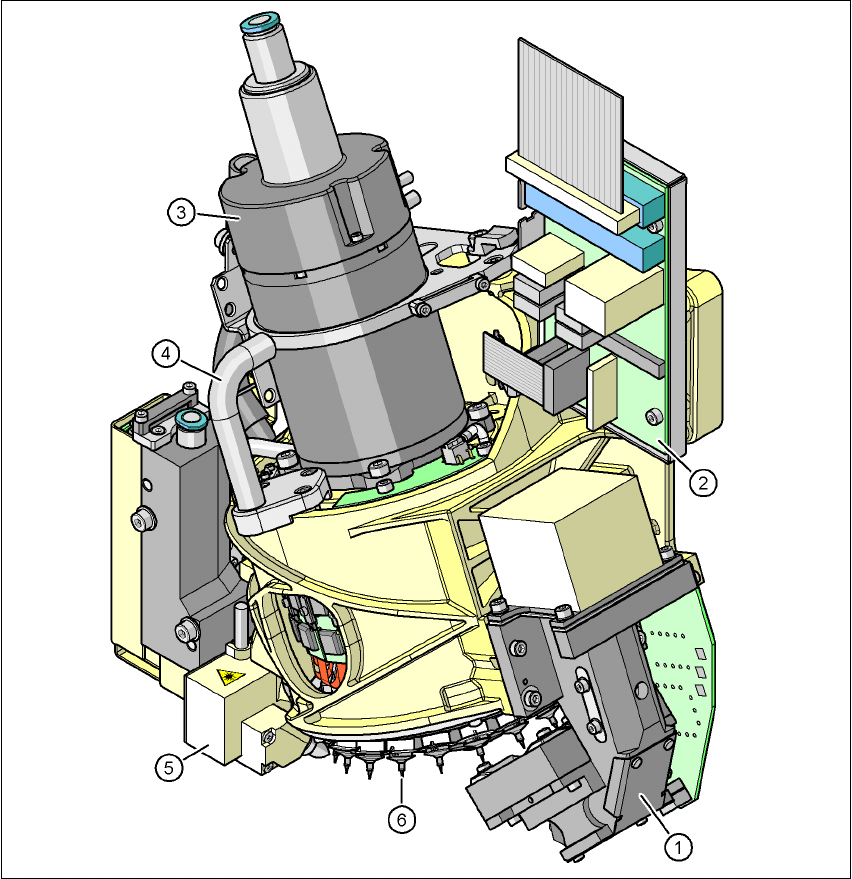
Fig. 3.7 - 5 20-segment Collect&Place head - Function groups, part 2
(1) C&P component camera, type 23, 6 x 6, digital
(2) Intermediate distributor board
(3) Star motor
(4) Handle
(5) Component sensor
(6) Star with 20 nozzles
3 Technical data User manual SIPLACE X-Series
3.7 Placement heads Software Version SR.601.xx 11/2005 US Edition
122
3.7.2.1 Description
The 20-segment Collect & Place head works on the Collect&Place principle. This means that,
within each cycle, twenty components are picked up by the placement head. At the pick-up and
placement position the component sensor checks that the component is present at the nozzle. On
their way to the placement position the components are optically centered and rotated into the re-
quired placement angle. Finally forced air sets down the component gently and accurately on the
board.
The C&P head succeeds in considerably increasing the output of the placement head and thus of
the overall placement machine. The compact construction of the C&P20 head allows very short
cycle times. In this case, the star axis is at an angle to the PCB level. This geometry allows the
segments to be arranged in a very small space.
The CO camera is still integrated into the C&P20 head. This saves additional traveling distances
to external centering cameras. Each segment also has a separate DP drive for rotating the nozzle.
The nozzles are therefore no longer rotated into the correct position at a single head station. They
can be rotated into their placement position at any time and independently of one another.
Each segment has a separate vacuum generator. This greatly reduces the time taken to switch
between vacuum and air kiss. It also allows a vacuum check to be carried out in the holding circuit
for each individual nozzle.
The Z drive for the segments is implemented with a linear motor with linear path measuring sys-
tem, and is thus extremely precise. In the pick-up/placement position, the Z drive moves the seg-
ments up or down in the vertical direction.
3.7.2.2 Checking and self-learning functions
The reliability of the 20-segment Collect&Place head is increased by checking and self-learning
functions.
– The vertical axis for picking up and placing the components is driven by a linear motor.
The traversing path is detected optoelectronically by a linear path measuring system. A
sensor registers the relative movement between nozzle and segment while setting down
components, and sends a signal to the axis controller to regulate the position. With this
sensor stop method, differences in height during pick-up and any unevenness of the
board surface are compensated during placement. The average of the deviations during
the last 10 placement operations is taken into account when adapting the further stroke
and placement speeds. The programmed placement force always remains constant.
– A component sensor is installed on the 20-segment Collect & Place head to increase
placement reliability. At the pick-up and placement position, it checks that the component
is present at the nozzle and in addition the component edge ratio. In this way it is possible
to determine whether the component was picked up by the nozzle transversely or on
edge. The beam intensity is also checked regularly to avoid false measurements.