00194307-01_SAHF_Intern_1203_ENG.pdf - 第20页
3 Serv ice Gan tri es SIPLACE HF Replacing the Gantry [030 06781-xx ] 3-10 0019 4307- 01 Iss ue 12/2 003 Copyr igh t © 2 003 S ie mens D em atic SD EA 1 1 With the aid of a 1/1 00 plastic t hickness ga ug e, check the …
SIPLACE HF
Replacing the Gantry [03006781-xx]
Service
Gantries
3
Copyright © 2003 Siemens Dematic SDEA 1 00194307-01 Issue 12/2003 3-9
2
1
2
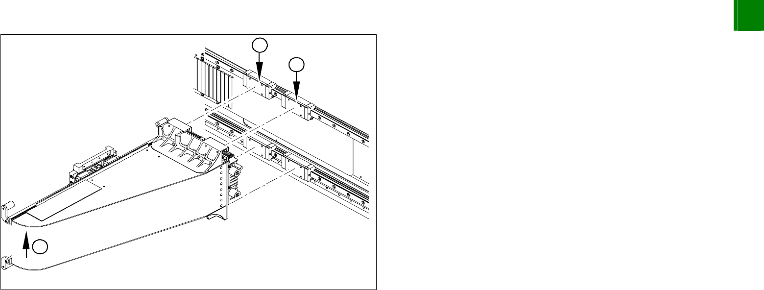
Do not tighten the fastening screws yet!
Lift the far end of the gantry (1) so that the gantry rests on the
contact edges of the top guide slide (2).
Tighten the top fastening screws.
Then tighten all 16 fastening screws with the aid of the special
torque wrench (9.5 N).
3
Service
Gantries
SIPLACE HF
Replacing the Gantry [03006781-xx]
3-10
00194307-01 Issue 12/2003 Copyright © 2003 Siemens Dematic SDEA 1
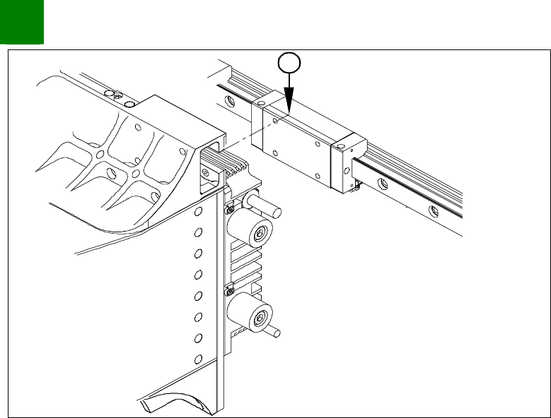
1
With the aid of a 1/100 plastic thickness gauge, check the gap
between the portal contact edge and the guide slide (1). The
gantry must lie flush with the guide slide, leaving no room in-
between for the thickness gauge.
If this is not the case, dismantle the gantry and clean the
contact surfaces again thoroughly (with the dressing stone).
SIPLACE HF
Replacing the Trailing Cable [03003706-xx]
Service
Gantries
3
Copyright © 2003 Siemens Dematic SDEA 1 00194307-01 Issue 12/2003 3-11
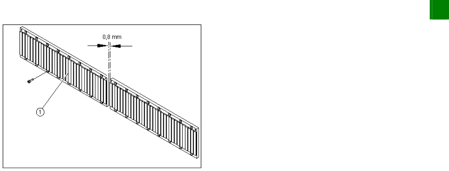
Install the magnetic strip (1).
Make sure there is a gap of 0.8 mm between two magnetic
strips.
Install the blue covers.
Install the cover plate for the magnet.
Install the trailing cable.
Install the PCB camera.
Reconnect to the electrical and pneumatic systems.
Fasten all electrical leads and pneumatic hoses at the correct
points.
Install all dismantled modules, covers and cover plates.
3.1.2 Replacing the Trailing Cable [03003706-xx]
Overview
The trailing cable is supplied as a fully assembled module. Depending upon the configuration of the machine, you will
need to remove the relevant modules, covers and cover plates before you can dismantle the trailing cable.