00194307-01_SAHF_Intern_1203_ENG.pdf - 第42页
3 Serv ice Gan tri es SIPLACE HF Replacing the X -Axis Read Head [030 06472] 3-32 0019 4307- 01 Iss ue 12/2 003 Copyr igh t © 2 003 S ie mens D em atic SD EA 1 3.1.5 Replacing the X-Axi s Read Head [03006 472] 1 1. Posit…
SIPLACE HF
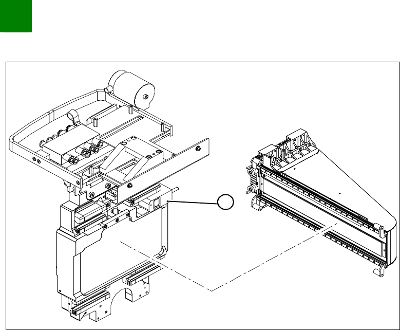
Replacing the X-Drive (Primary) [00375245-xx]
Service
Gantries
3
Copyright © 2003 Siemens Dematic SDEA 1 00194307-01 Issue 12/2003 3-31
3.1.4.1 Installation Checks for Guide Slide with Diaphragm Gland
Installation Check
1
3
2
From behind, shine a nonmagnetic Xenon flashlight between
the X-drive and the magnetic strip (1).
Between the motor support (2) and the guide slide (3) you
should see a gap.
If not, the X-drive must be dismantled again and remounted.
Check the distance between the X-drive and the magnet cover
with a 0.4 mm thickness gauge (plastic).
To do this, place the thickness gauge between the X-drive and
the magnet cover and then push the X-drive back and forth,
along the entire length - movement should be smooth with no
sticking or jamming.
3
Service
Gantries
SIPLACE HF
Replacing the X-Axis Read Head [03006472]
3-32
00194307-01 Issue 12/2003 Copyright © 2003 Siemens Dematic SDEA 1
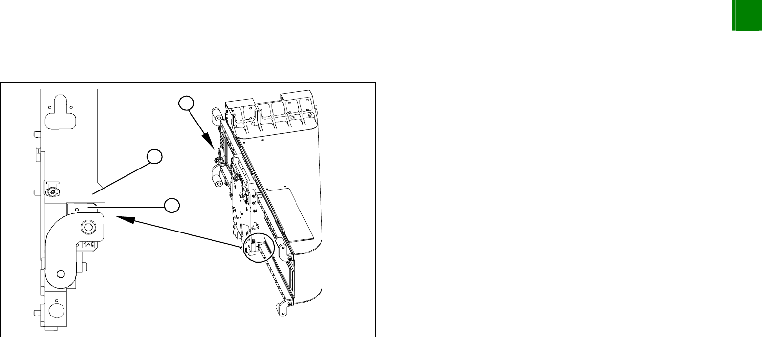
3.1.5 Replacing the X-Axis Read Head [03006472]
1
1. Position of the X-axis read head
SIPLACE HF
Replacing the X-Axis Read Head [03006472]
Service
Gantries
3
Copyright © 2003 Siemens Dematic SDEA 1 00194307-01 Issue 12/2003 3-33
5
1
3
2
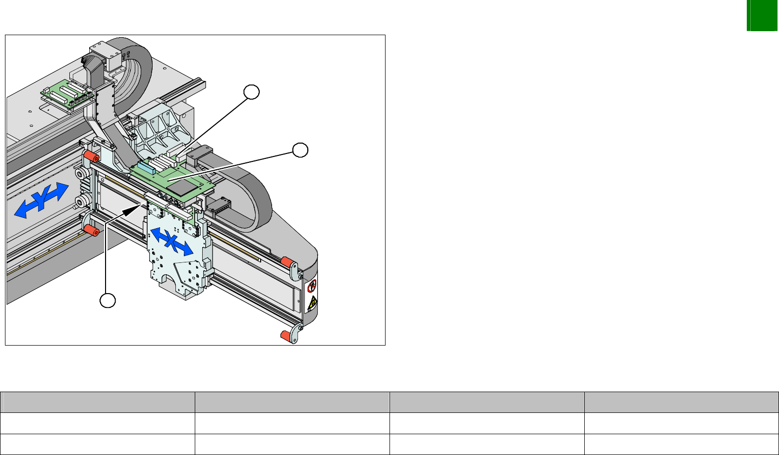
1. Vision board
2. Head interface (under the Vision board)
3. Read head position
Unplug the read head plug-and-socket connection from the
head interface (2).
Plug-and-Socket Connections
Assembly Gantry Board Terminal
X-axis read head Gantry 1 (DLM head) Head interface 03000901 X15ac
X-axis read head Gantry 2 (Twin head) Head interface 03000901 X15bc