00194307-01_SAHF_Intern_1203_ENG.pdf - 第22页
3 Serv ice Gan tri es SIPLACE HF Replacing the T railing Cable [03003706 -xx] 3-12 0019 4307- 01 Iss ue 12/2 003 Copyr igh t © 2 003 S ie mens D em atic SD EA 1 5 5 6 7 1 4 3 2 The flat ribbon cables a re r un from the…
SIPLACE HF
Replacing the Trailing Cable [03003706-xx]
Service
Gantries
3
Copyright © 2003 Siemens Dematic SDEA 1 00194307-01 Issue 12/2003 3-11
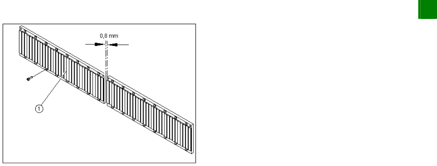
Install the magnetic strip (1).
Make sure there is a gap of 0.8 mm between two magnetic
strips.
Install the blue covers.
Install the cover plate for the magnet.
Install the trailing cable.
Install the PCB camera.
Reconnect to the electrical and pneumatic systems.
Fasten all electrical leads and pneumatic hoses at the correct
points.
Install all dismantled modules, covers and cover plates.
3.1.2 Replacing the Trailing Cable [03003706-xx]
Overview
The trailing cable is supplied as a fully assembled module. Depending upon the configuration of the machine, you will
need to remove the relevant modules, covers and cover plates before you can dismantle the trailing cable.
3
Service
Gantries
SIPLACE HF
Replacing the Trailing Cable [03003706-xx]
3-12
00194307-01 Issue 12/2003 Copyright © 2003 Siemens Dematic SDEA 1
5
5
6
7
1
4
3
2
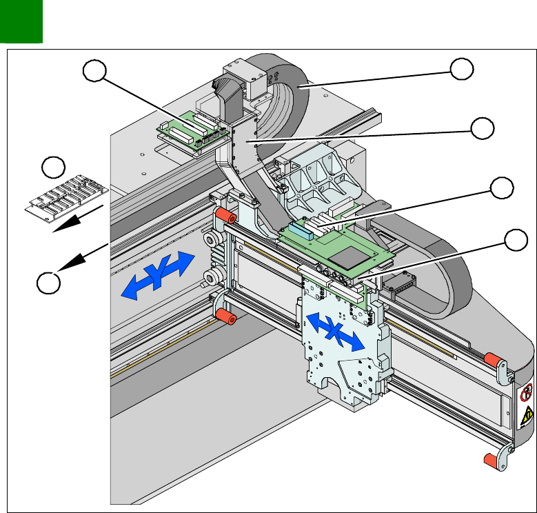
The flat ribbon cables are run from the head board (1), via
the trailing cable console (2) and the power track chain (3)
to the gantry interface (7) and the trailing unit interface
gantry (4).
The pneumatic hoses are run from the pneumatic
distributor (6), via the trailing cable console (2) and the
power track chain (3) to the gantry distributor (5) .
Where necessary, remove the cover plates from the gantry
trailing cable. Mark their exact position to ensure correct
replacement later.
SIPLACE HF
Replacing the Trailing Cable [03003706-xx]
Service
Gantries
3
Copyright © 2003 Siemens Dematic SDEA 1 00194307-01 Issue 12/2003 3-13
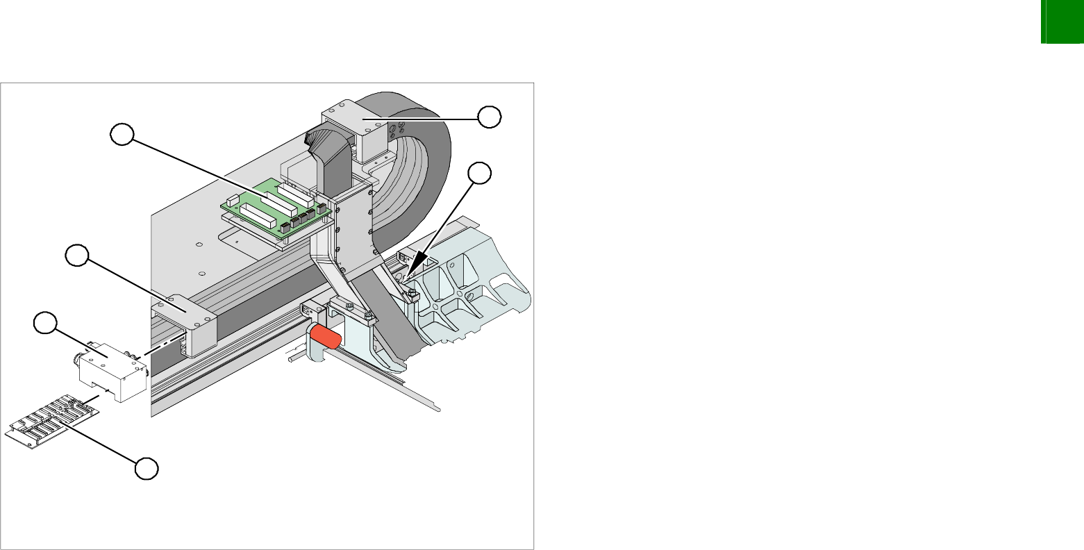
Disassembly
3
3
4
5
1
2
Disconnect the flat ribbon cable from the trailing unit interface
gantry (1). Take care not to lose the brackets for the plug-and-
socket connections.
Remove cable ties where necessary.
Disconnect the flat ribbon cable from the gantry interface (2).
Remove the cooling tubes (4) from the Y-axis motor.
Undo the screws fastening the pressure plates to the power
track chain. Please note that the screws have been secured
with loctite.
NOTE
Only undo the fastening screws. The clamps for the flat ribbon cable
remain in place.
Remove the cover from the gantry distributor (5).
Undo the two screws fastening the gantry distributor (5).
NOTE
Then disconnect the hoses from the gantry distributor. Now connect
the gantry distributor to the new trailing cable and reinstall the
distributor in the machine.
Secure the end of the trailing cable (with cable ties) in the
machine to prevent it hanging loosely and damaging other
machine components.