00194307-01_SAHF_Intern_1203_ENG.pdf - 第46页
3 Serv ice Gan trie s SIPLACE HF Replacing the X - Axis Read Head [030 06472] 3-36 0019 4307- 01 Iss ue 12/2 003 Copyr igh t © 2 003 S ie mens D em atic SD EA 1 1- 3.1.5.1 Adjusting the Grub Screw (tr ained service per s…
SIPLACE HF
Replacing the X-Axis Read Head [03006472]
Service
Gantries
3
Copyright © 2003 Siemens Dematic SDEA 1 00194307-01 Issue 12/2003 3-35
Installation
4
3
1
2
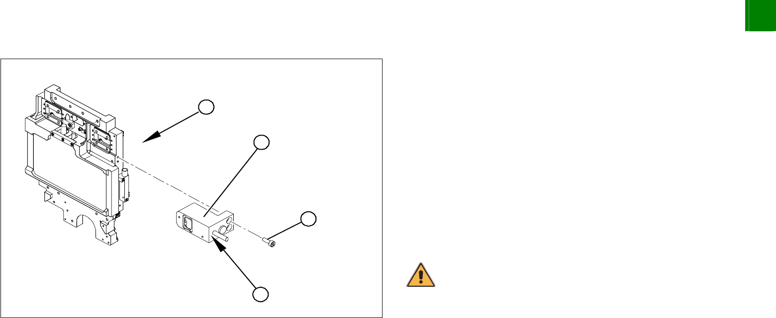
1. Head mount - front view
Loosely fasten the read head (2) with three screws (3).
The read head must be aligned with a 0.4 mm gap to the scale.
Use the corresponding thickness gauge (plastic).
You must also set the exact height to the scale. Align the read
head with the aid of the casting marks provided.
Tighten the fastening screws.
Reconnect to the electricity supply.
Make sure that the cables do not rub against anything. Fasten
them with cable ties.
CAUTION
Make sure that the axes can be moved without damaging the cables.
3
Service
Gantries
SIPLACE HF
Replacing the X-Axis Read Head [03006472]
3-36
00194307-01 Issue 12/2003 Copyright © 2003 Siemens Dematic SDEA 1
1-
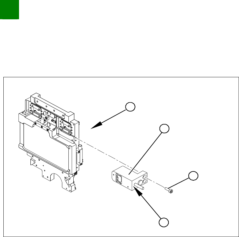
3.1.5.1 Adjusting the Grub Screw (trained service personnel only!)
Long Allen wrench size 1.5 for the grub screw on the read head
Varnished grub screw or locking varnish (Loctite No. 243)
4
3
1
2
Use the long Allen wrench (no ball head) to loosen the grub
screw (4) on the read head (2). The grub screw applies
pressure to the head mount and prevents unwanted movement
of the read head.
Remove the grub screw (4) and apply a little locking varnish
(Loctite No. 243) to it.
Screw the grub screw back in (4) until you are almost at the end
of the thread.
Install the read head (2) with the three fastening screws (3) so
that there is a gap of 0.4 mm between the read head and the
scale. Use the corresponding thickness gauge (plastic).
Tighten the grub screw (4) until you feel a slight resistance (not
too tight).
The read head is now fastened correctly.
SIPLACE HF
Replacing the Toothed Belt for the Width Adjustment System Drive [00369662-xx]
Service
Modular PCB Conveyor System
3
Copyright © 2003 Siemens Dematic SDEA 1 00194307-01 Issue 12/2003 3-37
3.2 Modular PCB Conveyor System
3.2.1 Replacing the Toothed Belt for the Width Adjustment System Drive [00369662-xx]
Tools
3 small or medium screw clamps
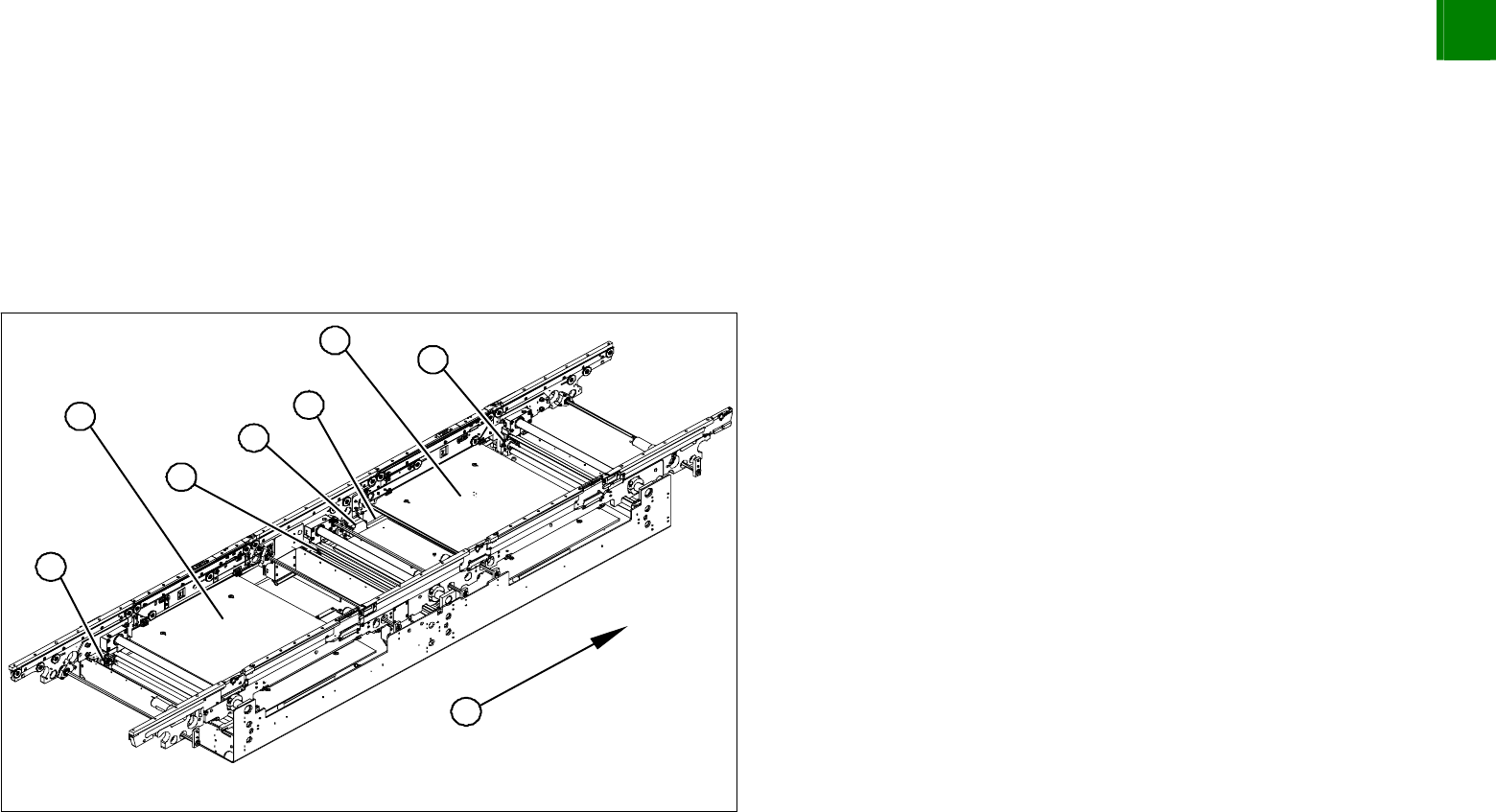
Overview
1
1
2
4
4
1
5
3
1. Adjustment units 1,2 and 3 with ball screws
2. Stepping motor for width adjustment system
3. Toothed belt for the drive
4. Lifting table plates BB1 and BB2
5. Direction of transport
Move the conveyor system to minimum width.
Undo the screws fastening the lifting table plates and remove
the lifting table plates from the lifting table unit.