00194307-01_SAHF_Intern_1203_ENG.pdf - 第44页
3 Serv ice Gan tri es SIPLACE HF Replacing the X -Axis Read Head [030 06472] 3-34 0019 4307- 01 Iss ue 12/2 003 Copyr igh t © 2 003 S ie mens D em atic SD EA 1 Disassemb ly 4 3 1 2 1. Head mou nt - front vi ew 2. Read he…
SIPLACE HF
Replacing the X-Axis Read Head [03006472]
Service
Gantries
3
Copyright © 2003 Siemens Dematic SDEA 1 00194307-01 Issue 12/2003 3-33
5
1
3
2
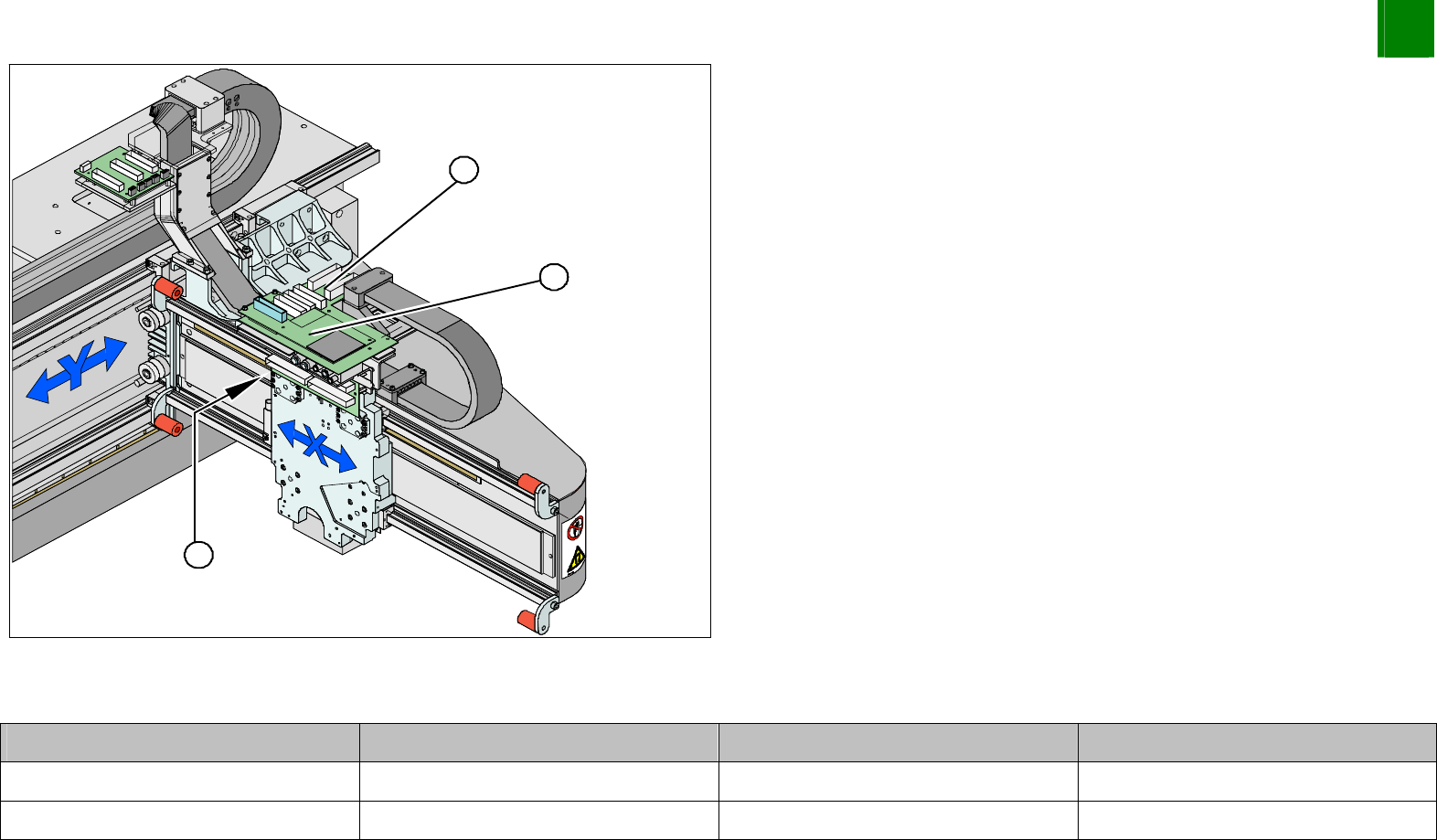
1. Vision board
2. Head interface (under the Vision board)
3. Read head position
Unplug the read head plug-and-socket connection from the
head interface (2).
Plug-and-Socket Connections
Assembly Gantry Board Terminal
X-axis read head Gantry 1 (DLM head) Head interface 03000901 X15ac
X-axis read head Gantry 2 (Twin head) Head interface 03000901 X15bc
3
Service
Gantries
SIPLACE HF
Replacing the X-Axis Read Head [03006472]
3-34
00194307-01 Issue 12/2003 Copyright © 2003 Siemens Dematic SDEA 1
Disassembly
4
3
1
2
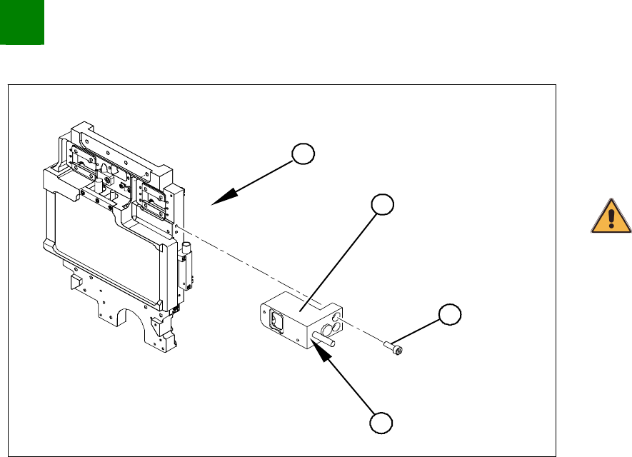
1. Head mount - front view
2. Read head
3. Fastening screws
4. Grub screws for fastening
CAUTION
Do not loosen or unscrew the grub screw (4).
Unthread the connection cable as far as the read head (2).
Undo the three screws (3) fastening the X-axis read head (2)
and carefully lift off the read head.
SIPLACE HF
Replacing the X-Axis Read Head [03006472]
Service
Gantries
3
Copyright © 2003 Siemens Dematic SDEA 1 00194307-01 Issue 12/2003 3-35
Installation
4
3
1
2
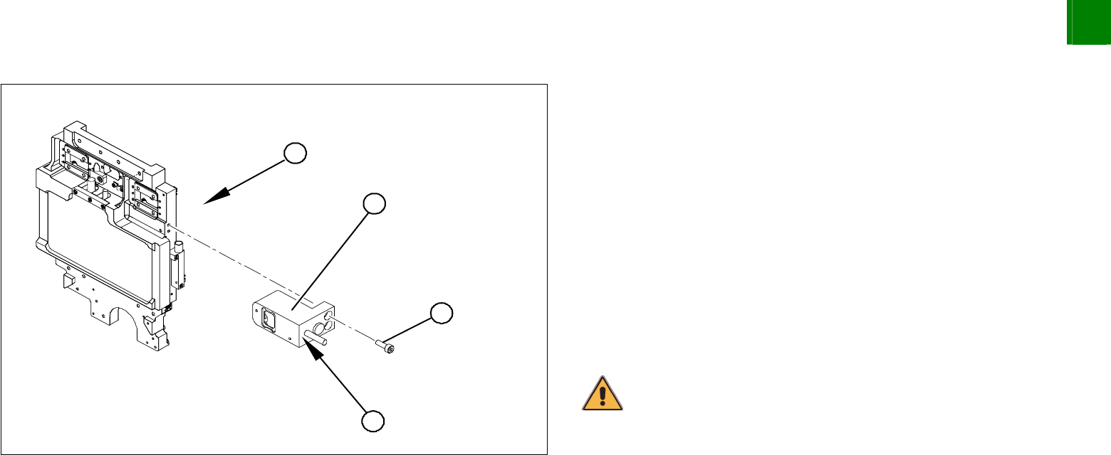
1. Head mount - front view
Loosely fasten the read head (2) with three screws (3).
The read head must be aligned with a 0.4 mm gap to the scale.
Use the corresponding thickness gauge (plastic).
You must also set the exact height to the scale. Align the read
head with the aid of the casting marks provided.
Tighten the fastening screws.
Reconnect to the electricity supply.
Make sure that the cables do not rub against anything. Fasten
them with cable ties.
CAUTION
Make sure that the axes can be moved without damaging the cables.