00194307-01_SAHF_Intern_1203_ENG.pdf - 第52页
3 Serv ice Modular PCB Convey or System SIPLACE HF Replacing the T oot h ed Belt fo r the Width Adju stment System Driv e [00369662-xx] 3-42 0019 4307- 01 Iss ue 12/2 003 Copyr igh t © 2 003 S ie mens D em atic SD EA 1 3…
SIPLACE HF
Replacing the Toothed Belt for the Width Adjustment System Drive [00369662-xx]
Service
Modular PCB Conveyor System
3
Copyright © 2003 Siemens Dematic SDEA 1 00194307-01 Issue 12/2003 3-41
1
1
5
4
3
2
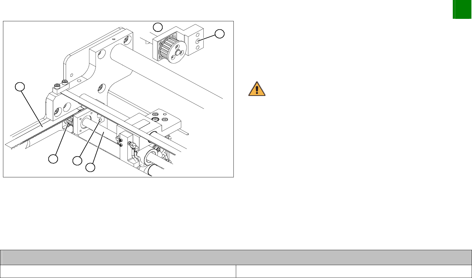
Remove the screw (1) fastening the ball screw and flange to the
base.
(Pos. 5 shows a rear view)
Remove the spindle (2) from its hole; the drive toothed belt (3)
can now be run out over the toothed wheels (4).
CAUTION
Make sure that the screw clamps are firmly attached.
Remove the complete drive toothed belt from the machine.
Thread the new toothed belt into the machine and run it over
the toothed wheels.
Install the flange and ball screw.
Run the drive toothed belt over the stepping motor deflection
pulley and install the stepping motor.
Tension the drive toothed belt.
Position the measuring point of the belt tension device at the
strand center of placement area 1 of the drive toothed belt.
Set the tension of the drive toothed belt according to the
following values.
Belt tension- width adjustment system
Drive toothed belt 30 Hz +/- 2 Hz
3
Service
Modular PCB Conveyor System
SIPLACE HF
Replacing the Toothed Belt for the Width Adjustment System Drive [00369662-xx]
3-42
00194307-01 Issue 12/2003 Copyright © 2003 Siemens Dematic SDEA 1
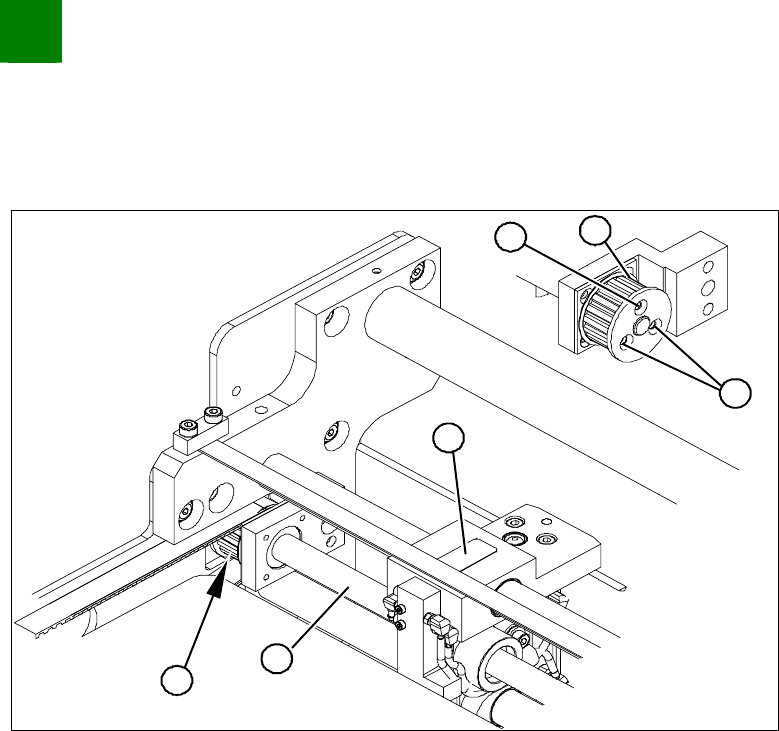
3.2.1.1 Resetting the Parallelism of the Adjustment Unit
If a ball screw and adjustment unit have twisted out of position (the conveyor system will no longer run parallel), please
proceed as follows:
1
1
2
4
3
2
Unscrew the three fastening screws (2) on the toothed wheel
(1).
The ball screw (3) and adjustment unit (4) can now be manually
turned (hold onto the toothed wheel and revolve the ball screw).
Measure the distance between a fixed adjustment unit and the
fixed conveyor side.
Turn the loose ball screw (3) until the adjustment unit (4) is set
to this value.
Fix the position with the 3 fastening screws (2) on the toothed
wheel (1).

Index
Copyright © 2003 Siemens Dematic SDEA 1 i
Index
Ball screws 3-39
Belt tension
Width adjustment 3-41
Cooling tubes 3-13
Diaphragm gland 3-22
Gap 3-31
Dressing stone 3-7
Drive toothed belt 3-41
Ethanol 3-7
Excenter axis 3-40
Flashlight
Xenon 3-31
Flat ribbon cable 3-13
Forcing screws 3-26
Guide slide 3-6
Head adapter board 3-2
Head board 3-2
Insulating plates 3-20
Locking screw 3-26
Loctite 3-13
Loctite 241 3-17, 3-20, 3-30
Magnet cover 3-5
Pneumatic hoses 3-24
Pressure plates 3-3, 3-13
Screw clamps 3-37
Sliders 3-38
Thickness gauge 3-10
Torque wrench 3-1, 3-20
Trailing cable 3-11
Trailing cable console 3-3, 3-12
X-drive 3-2
X-drive 3-23