00194307-01_SAHF_Intern_1203_ENG.pdf - 第32页
3 Serv ice Gan tri es SIPLACE HF Replacing the X -Drive (Prima ry) [00375245 -xx] 3-22 0019 4307- 01 Iss ue 12/2 003 Copyr igh t © 2 003 S ie mens D em atic SD EA 1 Prior Checks Check whethe r the machine is equipp ed wi…

SIPLACE HF
Replacing the X-Drive (Primary) [00375245-xx]
Service
Gantries
3
Copyright © 2003 Siemens Dematic SDEA 1 00194307-01 Issue 12/2003 3-21
3.1.4 Replacing the X-Drive (Primary) [00375245-xx]
Required Equipment
X-drive service pack (00375245-xx)
X-drive
4 x forcing screw
8 x locking screw (M4x60)
Metal templates for twin head and DLM2
6 grub screws M4x6-ST
Thickness gauge (plastic) 0.4 mm (approx. 50 cm long and 10 cm wide)
Foam mat 500 mm x 50 mm x 20 mm
Xenon flashlight (nonmagnetic)
Torque wrench with Allen key adapter
Loctite 241
3
Service
Gantries
SIPLACE HF
Replacing the X-Drive (Primary) [00375245-xx]
3-22
00194307-01 Issue 12/2003 Copyright © 2003 Siemens Dematic SDEA 1
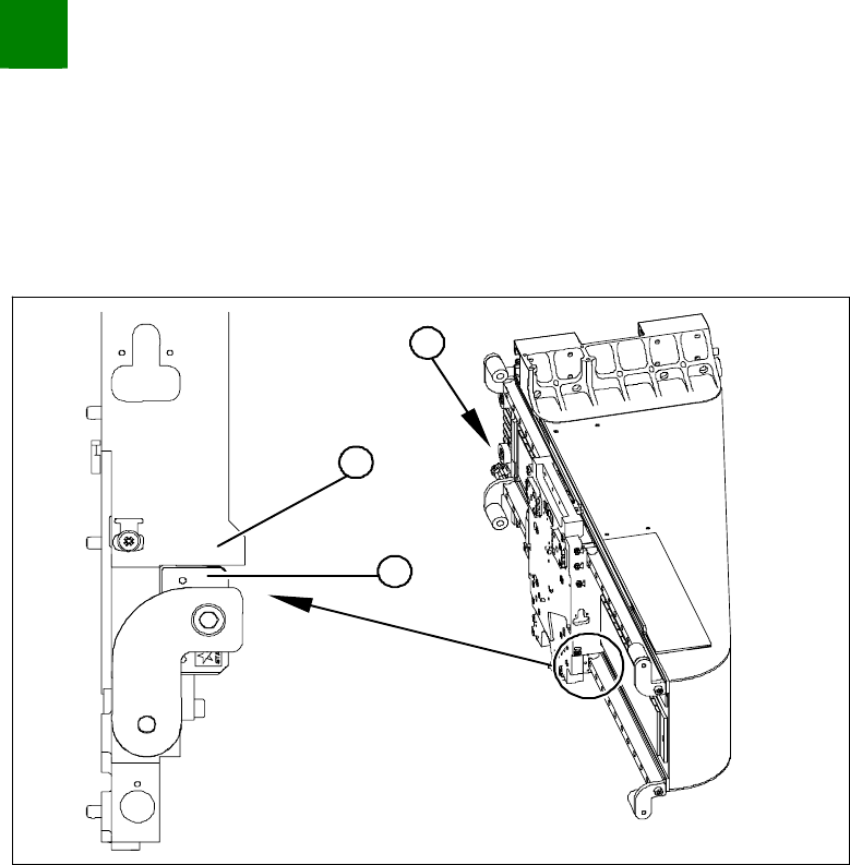
Prior Checks
Check whether the machine is equipped with a diaphragm gland or not.
Machines without diaphragm gland should not show any gap.
Machines with diaphragm gland must show a gap next to the stopper edge.
1
3
2
From behind, shine a nonmagnetic Xenon flashlight between
the X-drive and the magnetic strip (1).
Check the gap between the motor support (2) and the guide
slide (3).
SIPLACE HF
Replacing the X-Drive (Primary) [00375245-xx]
Service
Gantries
3
Copyright © 2003 Siemens Dematic SDEA 1 00194307-01 Issue 12/2003 3-23
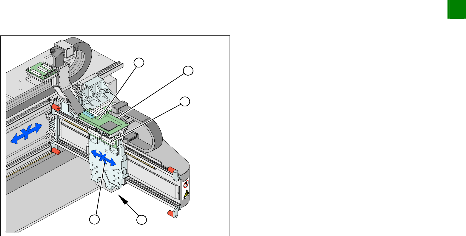
Disassembly
5
5
1 4
3
2
1. X-drive (primary) with head mount
2. X-mount with trailing cable
3. Head adapter board
4. Mount with PCB camera
5. Head board
Dismantle the placement head.
Remove the head adapter board (3). The x-mount fixtures are
now (2) accessible.
Unplug the following cables from the head board (5) and
remove them from the x-mount (2):
X motor cable
X-axis scanner head
Temperature sensor (if supplied).