YSP10_Mainte_E.pdf - 第101页
3. Conveyor transfer belt 4-12 Chapter 4 The parts to be replaced and its procedures 0 Check the belt as sembly condition. 1. Cl ose mach ine sa fety cover and l ower maintenance cover . Then close lower do or and cancel…
3. Conveyor transfer belt
4-11
Chapter 4 The parts to be replaced and its procedures
6
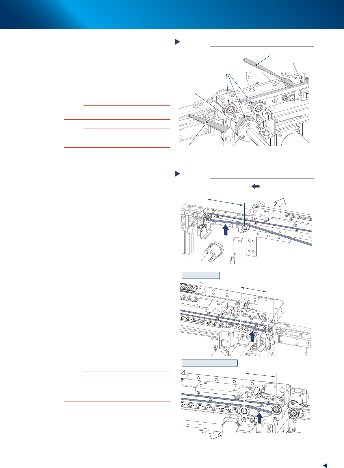
Clean the belt guides and the pulleys.
1. Use a vacuum assembly (option) to suction
the belt wear debris on the belt guides and
sensors, etc.
2. Use a plastic spatula or similar tool to
remove the belt wear debris adhering to the
outer peripheral surface of the pulleys.
3. Use a brush or similar tool to remove the
belt wear debris caught in the belt guides.
c
CAUTION
Use plastic spatula or brush to avoid scratching the pulley
or guide.
c
CAUTION
Do not use any solvent (such as IPA) except of heavy
soiling. Use absolute ethanol and make sure not to pour
the solvent over the pulley bearing upon cleaning.
7
Attach the new belt by the reversed
procedure of Step4 and Step5.
1. Attach the new belt temporarily while putting
it on the pulley.
2. Reattach the coupling and tighten the bolt.
3. Move the pulley bracket or the pulley to the
marked position and tighten temporarily.
8
Measure the belt tension at the tension
measurement point with the tension
meter as shown on the right illustration.
►
The belt tension standard value
Tension: 23 to 34N (256 to 305Hz)
►
Set values (tension meter)
Weight : 2.5(g/m, mm)
Width : 6(mm)
• For Standard machine
Span (datum side) : 111(mm)
Span (moving side) : 77(mm)
• For L650 type machine
Span (datum side) : 111(mm)
Span (moving side) : 70(mm)
9
According to the results of the belt
tension measurement, change the
tension adjustment plate position to
acquire the value in the optimal range.
Fix the temporarily tightened bolt firmly after
adjustment.
c
CAUTION
The tightening torque of the mouting bolt of center
conveyor is follwing. Make sure not to tighten the bolts
excessively.
Pulley mounting bolt : 5.5N·m
Pulley bracket mounting bolt : 5.5N·m
Cleaning of the belt guides and the pulleys
Step 6
Spatula
(made of plastic)
Outer peripheral surface of pulley
Brush
Example of the rear side of
the machine (moving side)
Belt guide
Belt wear debris
sticking to pulley
53435-KMJ-00
Step 8
■ Moving side
■ Datum side
SPAN 111mm
SPAN 77mm
SPAN 70mm
Tension measurement
:Tension measurement point
Front side of
machine
Front side of
machine
Standard conveyor
L650 type machine conveyor
53436-KMJ-10
3. Conveyor transfer belt
4-12
Chapter 4 The parts to be replaced and its procedures
0
Check the belt assembly condition.
1. Close machine safety cover and lower
maintenance cover. Then close lower door
and cancel the emergency stop.
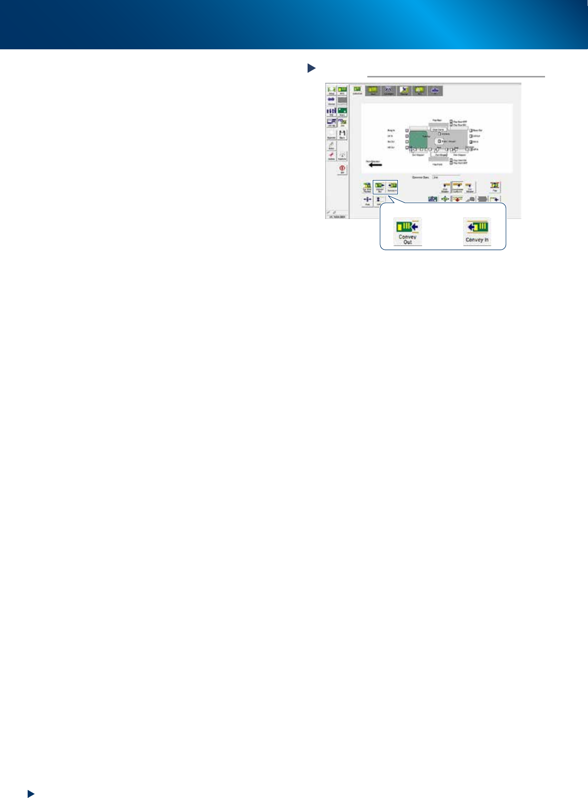
2. Press again the [Cleaner Connect] button on
[Unit] - [Cleaner] screen.
The cleaning unit moves to its original
position (machine front side) and disconnects
with the camera unit.
3. Press the [Convey In] or [Convey Out] button
on [Unit] - [Conveyor] screen to transfer
several boards, and check the motion.
4. Rotate the conveyor belt by hand and
confirm that no slack or unevenness of
rotation is found.
When any slack or unevenness of rotation is
found, check the belt assembly condition,
and readjust the position of pulley bracket
(or pulley).
Checking the transfer motion
Step 10
[Convey Out] button [Convey In] button
54401-KMJ-00
4. Mask vacuum unit
4-13
Chapter 4 The parts to be replaced and its procedures
4. Mask vacuum unit
This section describes the procedures for cleaning and replacing the mask vacuum filter of YSP10.
4.1 Cleaning and replacing the mask vacuum filter
e
1
Open the lower door.
1. Press the emergency stop button to open the
safety cover.
2. Open the lower door.
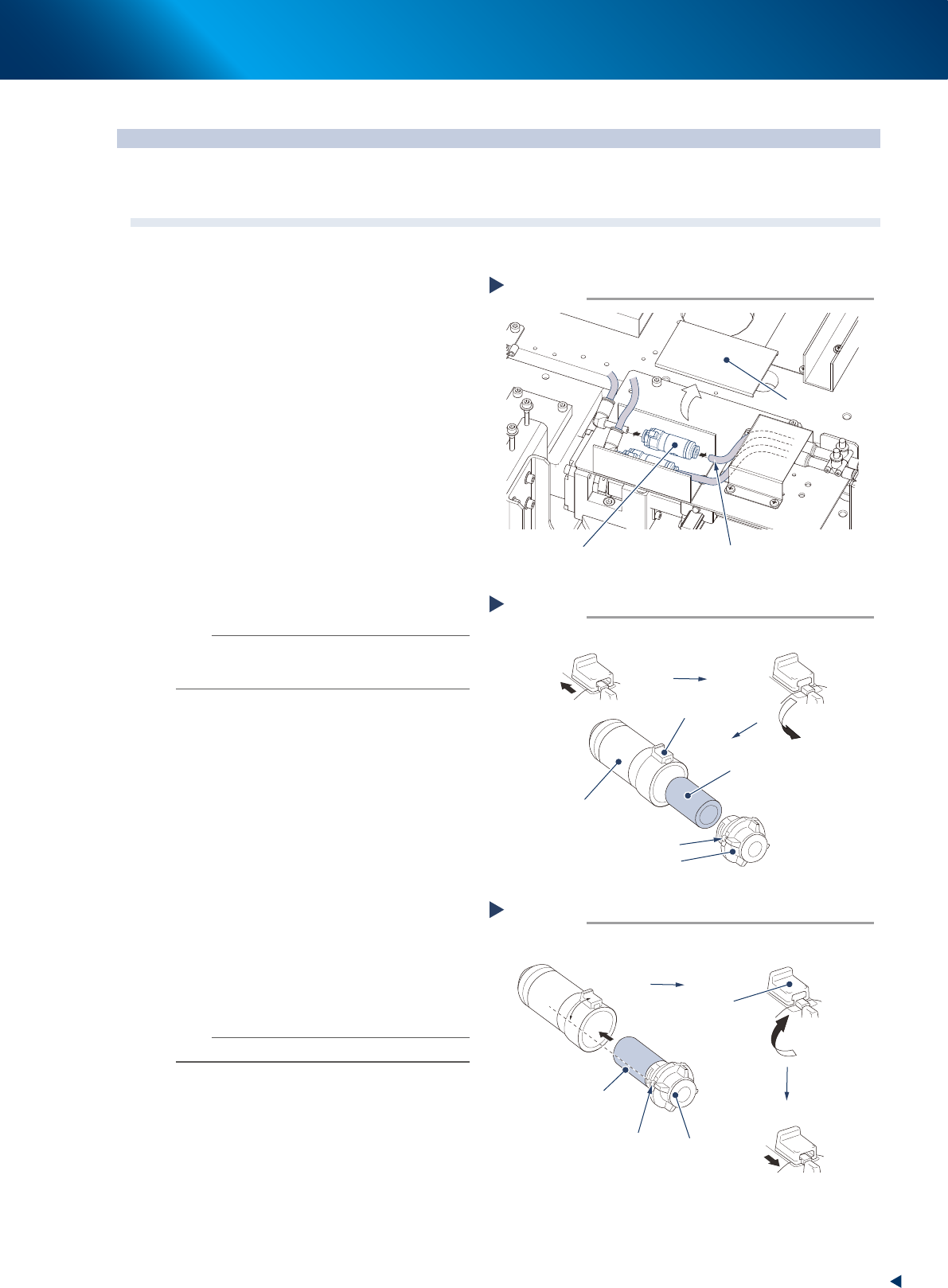
2
Remove the lter unit by detaching the
duct cover and pulling out the air hose
from the lter unit.
3
Take out the lter from the lter unit.
1. Slide the rotation stopper to arrow direction
to unlock.
2. Rotate the cover to counterclockwise 90
degrees or more.
3. Pull out the cover from the case to take out
the filter element.
4
Blow to clean the taken out lter inside
and outside with air blow tool.
n
NOTE
If dust cannot be removed or the filter has worn out,
replace the filter with a new one (KGR-M4995-F0X,
FILTER, SPACE).
5
Attach the lter to lter unit.
1. Attach the cleaned or new filter to the cap
to insert into the case.
2. Align the projection of the cover to the
position from 45 degrees counterclockwise
of the rotation stopper, and insert it until it
touches to the bottom.
3. Rotate the cap clockwise to align with the
rotating stopper.
4. Return the rotation stopper to the locked
position, and make sure that the cover is
firmly locked.
6
Reattach the lter unit.
1. Attach the joints on both sides of filter unit
to the air hose.
2. Return the duct cover to its original position.
n
NOTE
Attach the filter unit with care of its direction.
Removing the filter unit
Step 2
Filter unit
Air hose
Duct cover
53381-KMJ-00
Taking out the filter
Step 3
Filter
Cap
Projection of cap
Slide the rotation stopper
Case
Rotation stopper
Rotate the stopper 90 degrees or more
53438-KMJ-00
Attaching the filter
Step 5
Cap
Projection of cap
45°
Rotate to the rotation stopper
Insert the filter
Filter inserted into the cap
Rotation
stopper
Lock the cap
53439-KMJ-00