YSP10_Mainte_E.pdf - 第124页
1.Specication A-8 Appendix ► The list of inverter error code n NOTE When some error occurs on the inver ter , check the err or code on the LED panel from t he table below, contact to our sales representatives. Code Ala…
1.Specication
A-7
Appendix
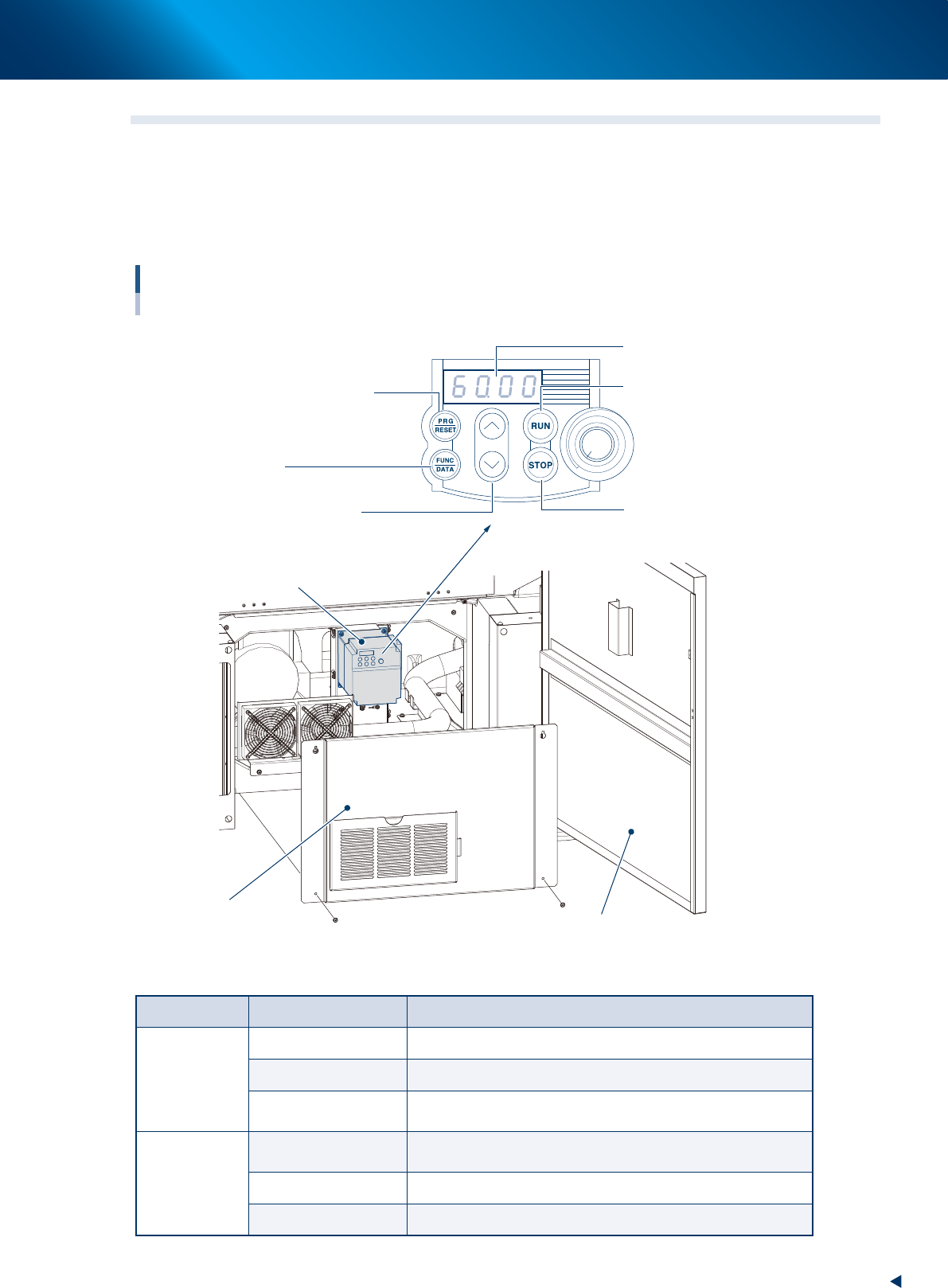
1.5 Inverter
The suction unit in the YSP10 machine uses the inverter. When the defect occurs in the inverter or the
suction motor, the error message appears on the operating display of the machine.
To check the error code displayed on the inverter, open the lower door of the front side of YSP10, remove
the inner cover as described in the illustrations below. Then the error code displayed on the LED panel can
be seen.
Inverter
For suction unit
Lower door of the front side
Inner cover (Front lower door)
Program/reset key
(See the table below)
Control panel
LED panel
Start key
Starts the motor
Select from setting items,
change the function code data etc.
Stop key
Stops the motor
Up/down key
Inverter
Function/data key
(See the table below)
53A08-KMJ-00
►
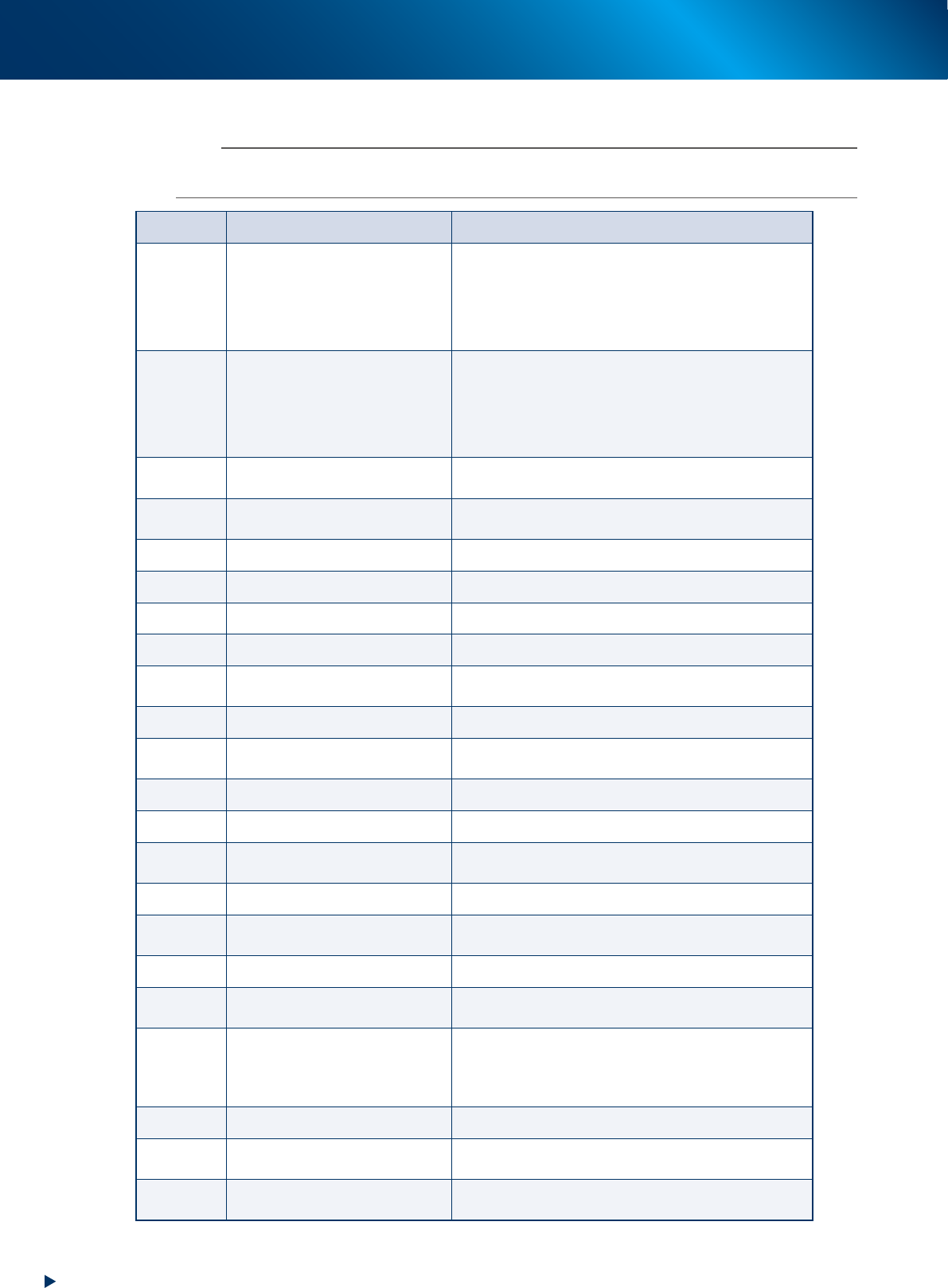
Details of the operating panel
Key name Operating mode Function description
PRG/RESET
Running mode Press this key to change to program mode.
Program mode Press this key to change to running mode.
Alarm mode
After clearing the cause of the alarm, press this key to release
the alarm and change to operating mode.
FUNC/DATA
Running mode
Switches monitors (output frequency, output current, and output
voltage etc.) on operating conditions.
Program mode Displays function code and fixes the data.
Alarm mode Displays details of alarm information.
1.Specication
A-8
Appendix
►
The list of inverter error code
n
NOTE
When some error occurs on the inverter, check the error code on the LED panel from the table below, contact to our sales
representatives.
Code Alarm name Case
0c1
0c2
0c3
Instant overcurrent
The instant value of the output current from the inverter
exceeds the overcurrent level.
Oc1: Overcurrent at acceleration
Oc2: Overcurrent at deceleration
Oc3: Overcurrent at fixed velocity
0u1
0u2
0u3
Overvoltage
The voltage of direct current intermediate circuit exceeds
the overvoltage detection level.
Ou1: Overvoltage at acceleration
Ou2: Overvoltage at deceleration
Ou3: Overvoltage at fixed velocity
lu
Undervoltage
The voltage of direct current intermediate circuit falls
below the undervoltage level.
lin
Input phase loss
Input phase loss, or power supplies interphases are
imbalanced largely.
0pl
Output phase loss Output phase loss occurs.
0h1
Overheat of cooling fin The temperature of the cooling fin rises.
0h2
External alarm The external alarm ("THR") is input.
0h4
Motor protection (PTC thermistor) The temperature of the motor get overheated.
0h6
Overheat of charging resistor
The internal charging resistor of the inverter get
overheated.
dbh
Overheat of braking resistor The thermal function for the braking resistor is actuated.
0l1/0l2
Overload of motor 1 / Overload of
motor 2
The electric thermal function for the motor 1 / motor 2,
which detects the overload of the motor, is actuated.
0lu
Overload of the inverter The temperature inside the inverter is overheated.
er1
Memory error It occurs some trouble (e.g. data writing error).
er2
Connection error of the touch
panel
The connection error occurs between the remote touch
panel (option) and the inverter.
er3
CPU error It occurs some trouble at CPU (e.g. runaway).
er6
Operation error
The wrong operation against the operating method
causes an error.
er7
Tuning error Failure of the auto tuning
er8
RS-485 communication error
The communication error occurs at RS-485
communication.
erf
Data save error by undervoltage
The commands which are set using touch panel like
frequency command, PID process command, timer
operating period, and "UP"/"DOWN" signals cannot be
saved correctly at the machine shutdown.
err
Simulated breakdown The "err" massage appears.
cof
Disconnection of PID feedback
wire detected
The signal wire of PID feedback is broken.
erd
Step-out detected (For driving
synchronous motor)
The step-out of the synchronous motor detected

2. Periodic inspection check sheet
A-9
Appendix
2. Periodic inspection check sheet
Use the inspection check sheet to perform the periodic inspection.
This check sheet contains weekly and monthly inspection items in addition to "daily inspection" items.
Copy and use the "Inspection check sheet (sample)" on the next page, or prepare and practice the format
like this check sheet.
█
Points for the inspection
►
The periodic inspection should be performed by the engineer who have completed YAMAHA
maintenance training, or under the instruction of that engineer.
►
Before greasing up, perform warm-up operation and wipe off the excess grease.