YSP10_Mainte_E.pdf - 第55页
2. Monthly maintenance 3-8 Chapter 3 Periodic maintenance items 5 Inject the grease to the CX-axis b all screw . Using a grease gun (standard nozzle), inject the pres cribe d grease (NSL) a t the grea se nippl e of the b…
2. Monthly maintenance
3-7
Chapter 3 Periodic maintenance items
2.5 CX-axis, CY-axis and cleaning unit
This section describes the procedures of cleaning and lubrication for CX-axis and CY-axis of camera unit.
Conduct same procedure for the cleaning unit at the same time because it is located on the CY-axis.
2.5.1 Cleaning and lubricating the CX-axis
The procedure to access to CX-axis varies between the standard type machine and the optional type
machine (installed "Automatic mask exchange unit" and/or "Universal mask holder").
This section describes each procedures of cleaning and lubricating CX-axis, for both "Standard type" and
"Optional type".
█
Standard type
1
Evacuate the squeegee unit by the work
from front side.
e
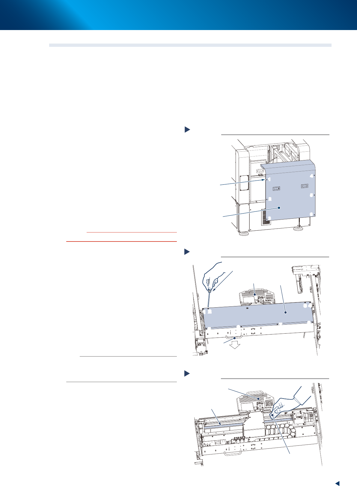
1. Press the emergency stop button and open
machine safety cover.
2. Move squeegee unit to machine front side
grabbing its handle.
2
Detach machine rear cover by the work
from rear side.
1. Loosen 6 screws on the rear cover of
machine with a Phillips screwdriver. Then
remove the cover uplifting.
c
CAUTION
Be careful not to be injured by dropping down the cover.
2. Holding the handle, evacuate the squeegee
unit to convenient position (front side) for the
work from rear side.
3
Remove the CX-axis cover by the work
from rear side.
Loosen 8 screws mounting CX-axis
cover with a Phillips screwdriver, then
remove the cover.
4
Clean the CX-axis ball screw.
1. Wipe away the grease or soiling of CX-axis
ball screw with lint-free cloth.
2. Move the camera unit to the opposite side
to clean the rest part.
n
NOTE
Wipe off carefully the lead groove area of the ball screw
and the groove area of the guide as well. Be sure that the
cloth, etc., being used to clean the ball screw does not
produce lint, etc.
Detaching machine rear cover
Standard type
Step 2
6 screws
Machine rear cover
1
2
3
4
5
6
1
2
3
4
5
6
53387-KMJ-00
Detaching CX-axis cover
Step 2,3
Phillips screwdriver
CX-axis cover
Handle
Machine rear side
Camera unit
1
2
3
4
5
6
7
8
1
2
3
4
5
6
7
8
53311-KMJ-00
Cleaning CX-axis ball screw
Step 4
Lint-free cloth
Camera unit
CX-axis ball screw
53312-KMJ-00
2. Monthly maintenance
3-8
Chapter 3 Periodic maintenance items
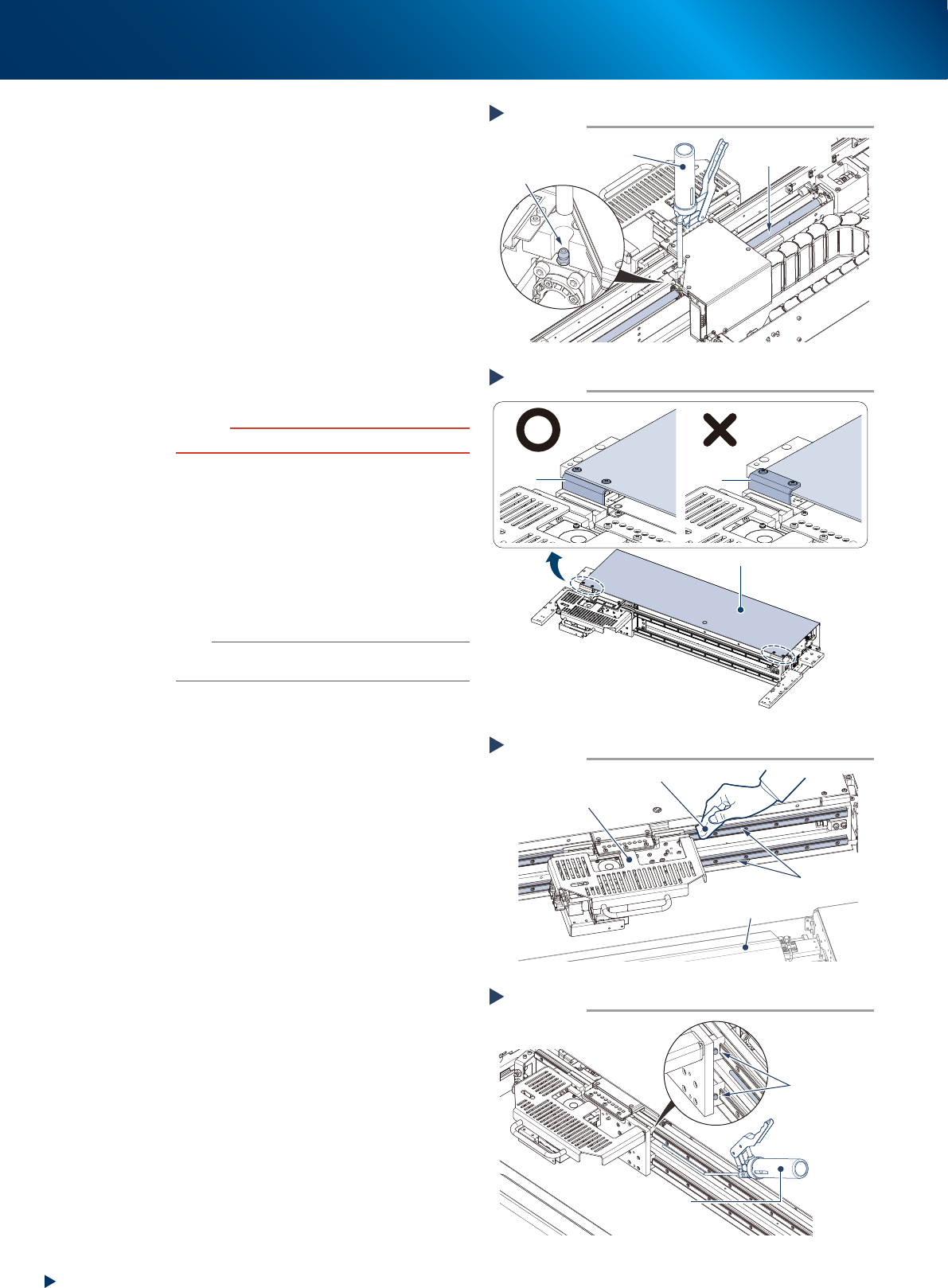
5
Inject the grease to the CX-axis ball
screw. Using a grease gun (standard
nozzle), inject the prescribed grease
(NSL) at the grease nipple of the ball
screw, until the grease begins to seep
out from the gap.
6
Wipe off the excess grease.
1. Move the camera unit left to right manually
to spread the grease.
2. Wipe off the excess grease from both ends
of the ball screw.
7
Reattach the cover.
1. Mount the CX-axis cover to its original
position with a Phillips screwdriver.
c
CAUTION
Mount CX-cover so that its front side covers bracket.
2. Mount the rear cover to its original position
with a Phillips screwdriver.
8
Clean the CX-axis guide by the work
from the front side.
1. Wipe the grease and soiling from the
CX-axis guide with lint-free cloth.
2. Move the camera unit to the opposite side,
then clean the rest part of the guide.
n
NOTE
Wipe off carefully the guide grooves. Additionally, make
sure that any dirt is not remained.
9
Inject the grease to the CX-axis guide.
Using a grease gun (bend type nozzle), inject
the prescribed grease (NSL) at the upper and
lower grease nipples of the guide.
There are 4 grease nipples on the both sides of
the camera unit.
0
Wipe off the excess grease.
1. Move the camera unit left to right manually
to spread the grease.
2. Wipe off the excess grease from the guide
block of the guide.
Lubricating CX-axis ball screw
Step 5
Grease gun
(standard type nozzle)
Grease nipple
CX-axis
Ball screw
53313-KMJ-00
Attaching CX-axis cover
Step 7
CX-axis coverCX-axis cover
CX-axis cover
Bracket
Bracket
53392-KMJ-00
Cleaning CX-axis guide
Step 8
Lint-free cloth
Camera unit
Cleaning unit
CX-axis guide
53314-KMJ-00
Lubricating CX-axis guide
Step 9
Grease gun
(bend type nozzle)
Grease nipple
53315-KMJ-00
2. Monthly maintenance
3-9
Chapter 3 Periodic maintenance items
█
Optional type
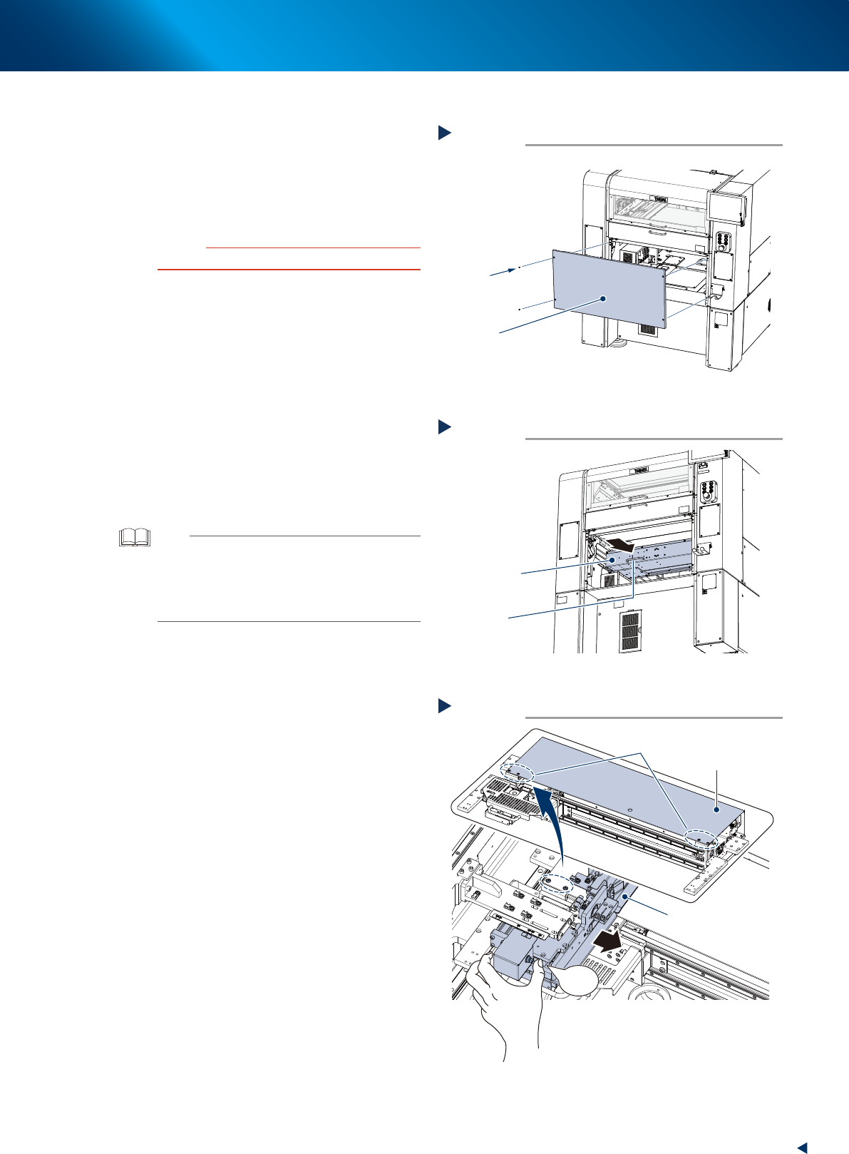
1
e
Detach machine safety cover.
1. Press the emergency safety button to ensure
the safety of work.
2. Remove 4 screws of center rear cover of
machine using Phillips screwdriver, then
detach center rear cover.
c
CAUTION
Be careful not to be injured by dropping down the cover.
2
Move camera unit to machine front side
grabbing its handle, by the work from
rear side.
3
Detach screws of CX-axis cover front
side by the work from front side.
1. Open machine safety cover.
2. Move the universal mask holder into
machine inside until the screws of CX-axis
cover front side can be seen, while pressing
the button illustrated at right.
3. Remove 4 screws of CX-axis cover front side
(2 screws each on left and right) using
Phillips screwdriver.
TIP
When the machine is installed "Standard (fixed) mask
holder (L736 x W736 or more)" and "Automatic mask
exchange unit", the detaching procedure of screws of
CX-axis cover front side is different.
See "Standard (fixed) mask holder (L736 x W736 or
more)" for details.
Detaching center rear cover
Optional type
Step 1
4 screws
Center rear cover
53388-KMJ-00
Move camera unit to machine front side
Machine rear side
Step 2
Handle
Camera unit
53389-KMJ-00
Detaching screws of CX-axis cover front side
Machine front side
Step 3
Universal mask holder
Move into machine inside while pressing the button
Screws on front side
(two each on left and right)
CX-axis cover
PUSH
53390-KMJ-00