YSP10_Mainte_E.pdf - 第61页
2. Monthly maintenance 3-14 Chapter 3 Periodic maintenance items 4 Mo ve the clea ning u nit an d camera u nit to mac hine rear side. c CAUTION Confirm there is no t ools etc. remained in machine. 1. Close mac hine safety…
2. Monthly maintenance
3-13
Chapter 3 Periodic maintenance items
2.5.2 Cleaning and lubricating the CY-axis and the cleaning unit
The CY-axis and the cleaning unit share the same guide. Therefore clean and lubricate these 2 units at once.
Moreover, machine rear cover of standard type machine and optional type machine (installed "Automatic
mask exchange unit") are different.
1
Detach machine rear cover.
e
Press the emergency stop button to ensure the
safety of maintenance work.
• Standard type:
Remove six screws on machine rear cover
using Phillips screwdriver and lift up to
detach the rear cover.
• With automatic mask exchange unit:
1. Open center rear cover.
2. Remove four screws on machine center
rear cover using Phillips screwdriver, then
detach center rear cover.
c
CAUTION
Be careful not to be injured by dropping down the cover.
2
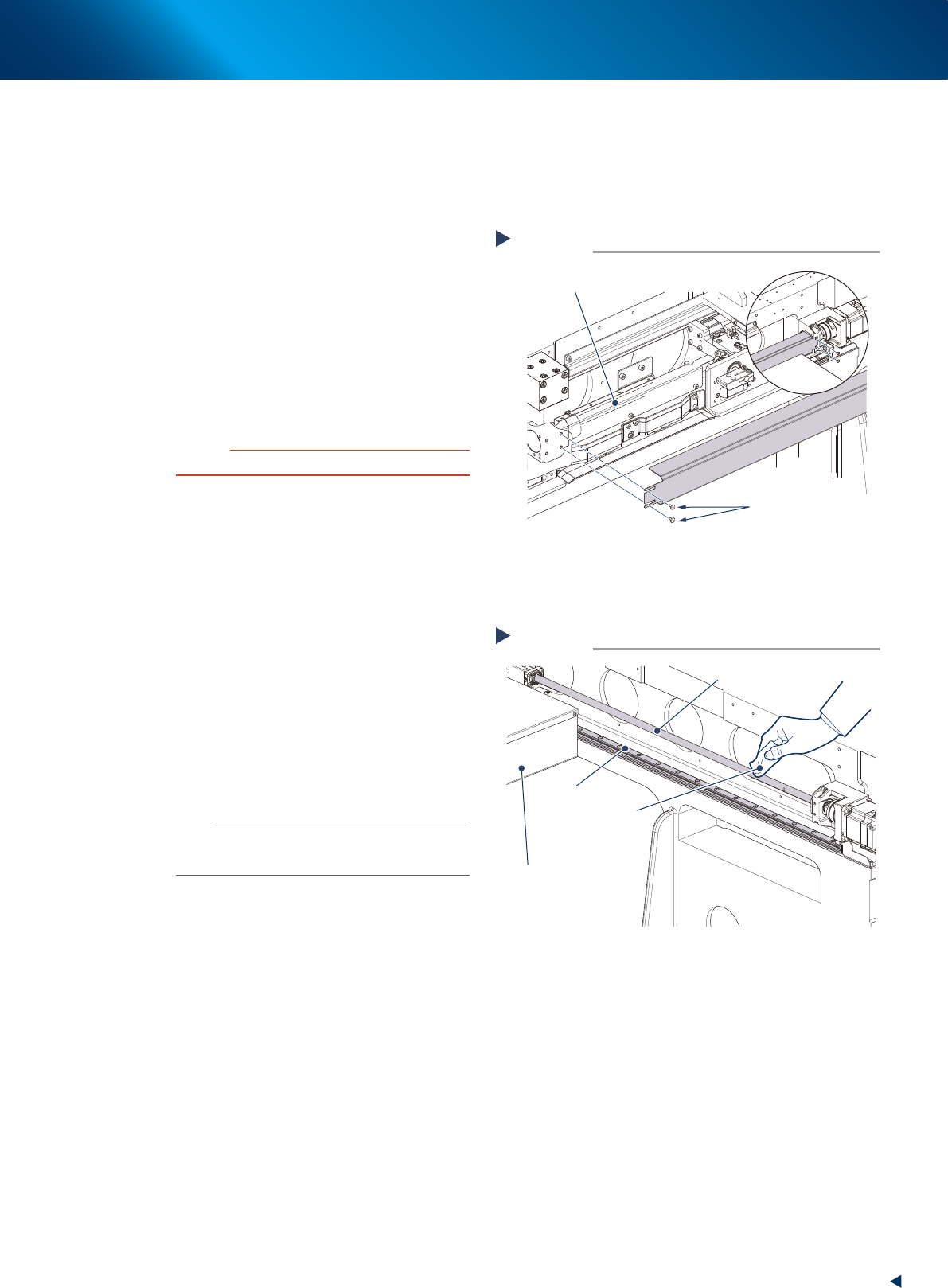
Remove the CY-axis ball screw cover.
1. Remove the 2 bolts (on machine rear cover)
mounting the CY-axis ball screw cover with
a hexagon wrench (2mm).
2. Open machine safety cover.
3. Remove 2 screws (on machine front)
mounting the CY-axis ball screw cover with
a hexagon wrench (2mm). Then pull out the
cover.
3
Clean the CY-axis by the work from rear
side.
1. Move the camera unit (CX-axis) to the
cleaning unit side.
2. Wipe the grease and soiling from the
CY-axis ball screw and CY-axis guide (2
positions each) with lint-free cloth.
n
NOTE
Carefully wipe the lead grooves and the guide grooves of
the ball screw. Additionally, make sure that any dirt is not
remained.
Removing the CY-axis cover
Step 2
CY-axis ball screw
Rear side
Mounting bolts
53316-KMJ-00
Cleaning the CY-axis from rear side
Step 3
CY-axis ball screw
CY-axis guide
Lint-free cloth
Camera unit
53317-KMJ-00
2. Monthly maintenance
3-14
Chapter 3 Periodic maintenance items
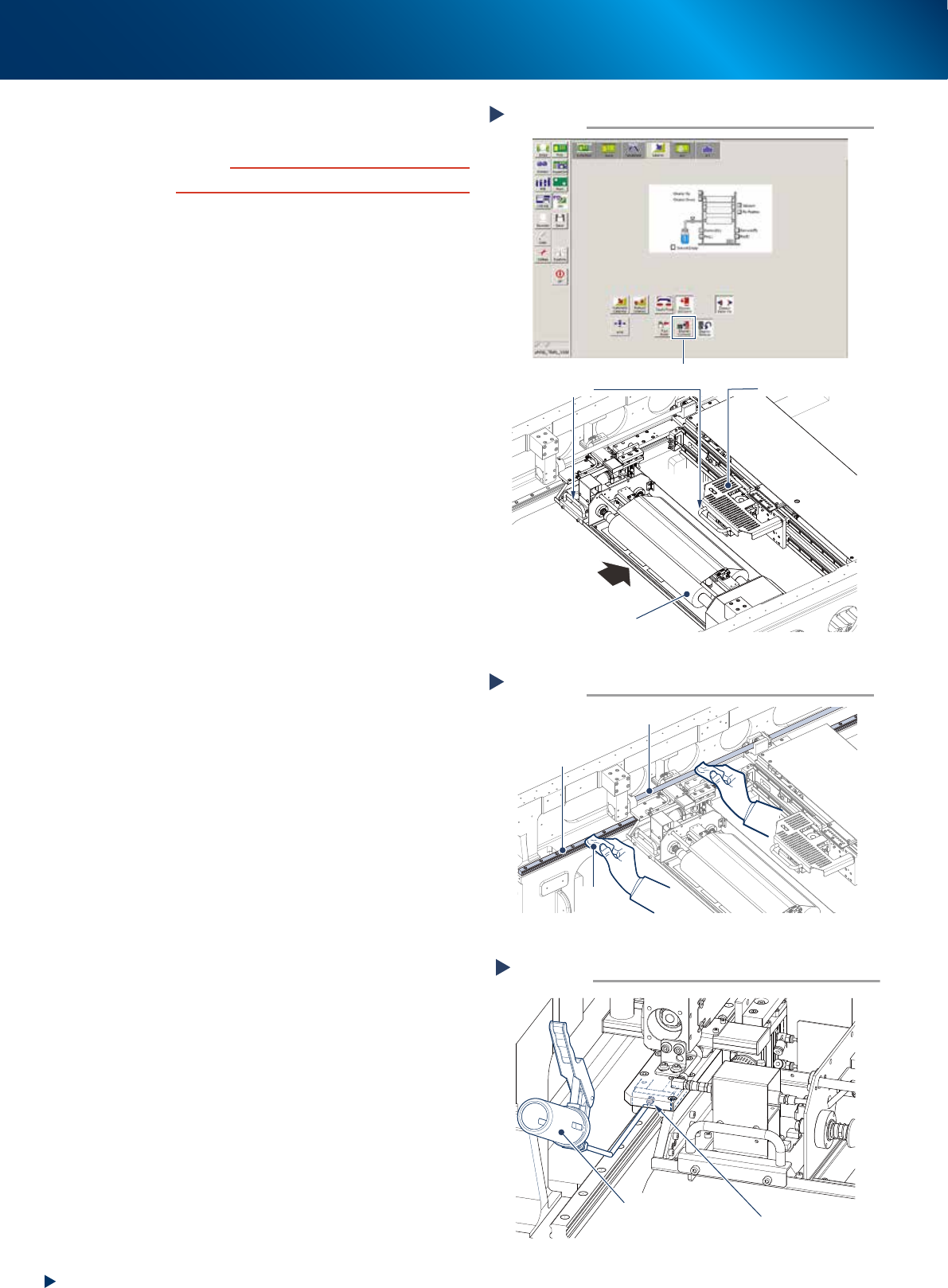
4
Move the cleaning unit and camera unit
to machine rear side.
c
CAUTION
Confirm there is no tools etc. remained in machine.
1. Close machine safety cover and rear upper
rear cover, then cancel the emergency stop.
2. Press the [Cleaner Connect] button on [Unit]
- [Cleaner] screen to connect the cleaning
unit and camera unit.
e
3. Press the emergency stop button and open
machine safety cover.
4. Move the cleaning unit and camera unit
grabbing a handle of cleaning unit or
camera unit.
5
Clean the CY-axis by the work from
front side.
Wipe the grease and soiling, left upon cleaning
from rear side.
6
Lubricate the CY-axis by the work from
front side.
1. Using a grease gun (bend type nozzle),
inject the prescribed grease (NSL) at the
grease nipples of the left and right guides,
until the grease seep out.
The grease nipples are positioned on the
both side.
2. Grab the connected cleaning unit and
camera unit and move it backward and
forward several times to spread the grease,
then wipe away excess grease.
7
Reattach the cleaning unit to its original
position.
1. Close machine safety cover and cancel the
emergency stop.
2. Press again the [Cleaner Connect] button on
[Unit] - [Cleaner] screen.
The cleaning unit returns to its original
position (machine front side) and disconnects
with the camera unit.
Moving cleaning unit and camera unit
Step 4
Press the [Cleaner Connect] button
Handle
Camera unit
Cleaning unit
Move to machine rear side
54346-KMJ-00
Cleaning CY-axis from front side
Step 5
CY-axis ball screw
CY-axis guide
Lint-free
cloth
53318-KMJ-10
Lubricating the cleaning unit
Step 6
Cleaning unit
grease nipple
Grease gun
(bent type nozzle)
53320-KMJ-00
2. Monthly maintenance
3-15
Chapter 3 Periodic maintenance items
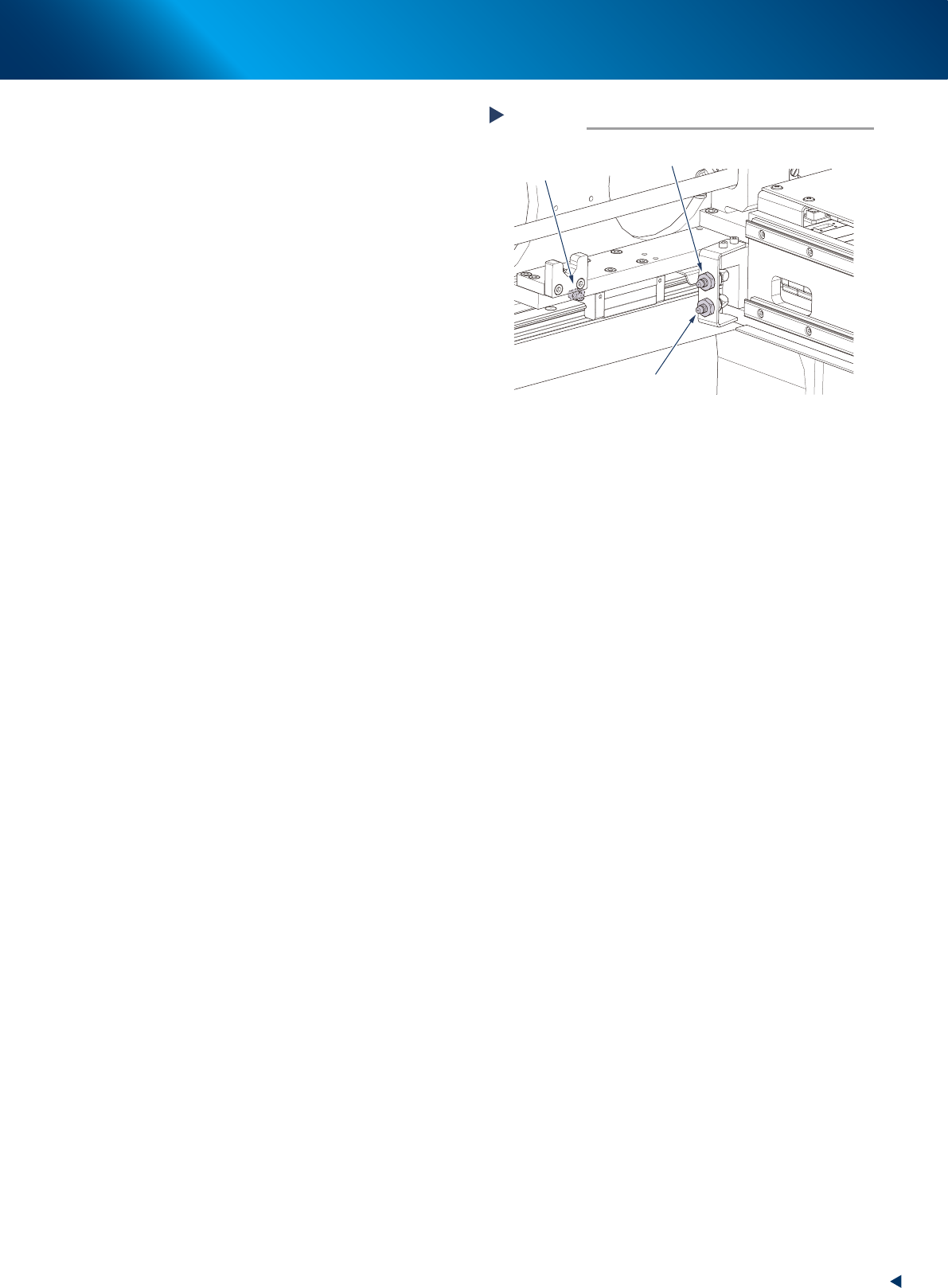
8
e
Lubricate the CY-axis.
1. Press the emergency stop button and open
machine safety button.
2. Change the nozzle of grease gun to the
standard type.
3. Move the camera unit to the position
convenient for lubrication by hand.
4. Inject the prescribed grease (NSL) at the
grease nipples of the ball screw (1 position)
and the guide (2 positions) until the grease
seep out from the gap.
The grease nipples are placed on both left
and right side.
5. Grab the handle of camera unit and move it
backward and forward several times, then
wipe away excess grease from the ball
screw and guide.
9
Reattach the CY-axis ball screw cover to
its original position with a Phillips
screwdriver.
Close machine safety cover.
0
Return the machine rear cover.
• Standard type:
Reattach the machine rear cover to its
original position using Phillips screwdriver.
• With automatic mask exchange unit:
Reattach the machine center rear cover to
its original position using Phillips screw-
driver.
Lubricating the CY-axis
Step 8
CY-axis guide
grease nipple
(at rear side)
CY-axis guide
grease nipple
(at front side)
CY-axis ball screw
grease nipple
53319-KMJ-00