YSP10_Mainte_E.pdf - 第71页
3. 3-month maintenance 3-24 Chapter 3 Periodic maintenance items 3.2 PU-axis T his section describes the procedures of cleaning and lubricating for PU-axis. 3.2.1 Cleaning and lubricating the PU-axis 1 Raise the PU-axis.…
3. 3-month maintenance
3-23
Chapter 3 Periodic maintenance items
9
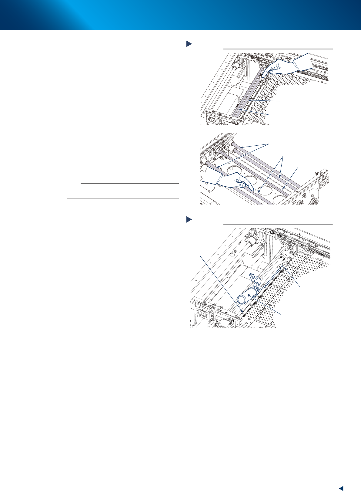
Apply grease to the ball screws and the
hexagon splines.
W2-axis
Apply the specified grease (NSL) by hand
uniformly over the surfaces of the ball screws (2
positions) and the hexagon spline (1 position)
and grooves.
W1- and W3-axes
Apply the specified grease (NSL) by hand
uniformly over the surfaces of the ball screws (2
positions each), the hexagon spline (1 position
each) and the shaft guides (2 position each)
and grooves.
0
Apply grease to the guide of W2-axis
with a grease gun.
Use a grease gun (bend type nozzle) to inject
the prescribed grease (NSL) at the grease
nipples (2 positions) of the guide.
n
NOTE
Inject until the grease begins to seep out from the gap
between guide block and guide.
q
Change the conveyor width to its
minimum width with the procedure of
Step4.
w
Apply grease to the rest of the ball
screws.
e
1. Press the emergency stop button to open
machine safety cover, lower door and
maintenance door.
2. Apply the specified grease (NSL) by hand
uniformly over the surfaces of the ball
screws and grooves where the grease could
not be applied in Step9.
e
Spread the grease.
1. Close maintenance door, lower door and
machine safety cover, and cancel the
emergency stop.
2. Change the conveyor width from maximum
to minimum several times with the
procedures of Step7 and 4.
r
Wipe away excess grease.
e
1. Press the emergency stop button and open
machine safety cover, lower door and
maintenance door.
2. Wipe all excess grease from the edge of
guide and ball screw with lint-free cloth.
Manual lubrication for W2-axis
Step 9
Hexagon spline
W2-axis ball screw
Hexagon spline
W1(3)-axis shaft guides
W1(3)-axis ball screws
53309-KMJ-00
Lubrication for W2-axis guide
Step 10
Grease gun
(bend type nozzle)
Grease nipple
W2-axis
guide
53310-KMJ-00
3. 3-month maintenance
3-24
Chapter 3 Periodic maintenance items
3.2 PU-axis
This section describes the procedures of cleaning and lubricating for PU-axis.
3.2.1 Cleaning and lubricating the PU-axis
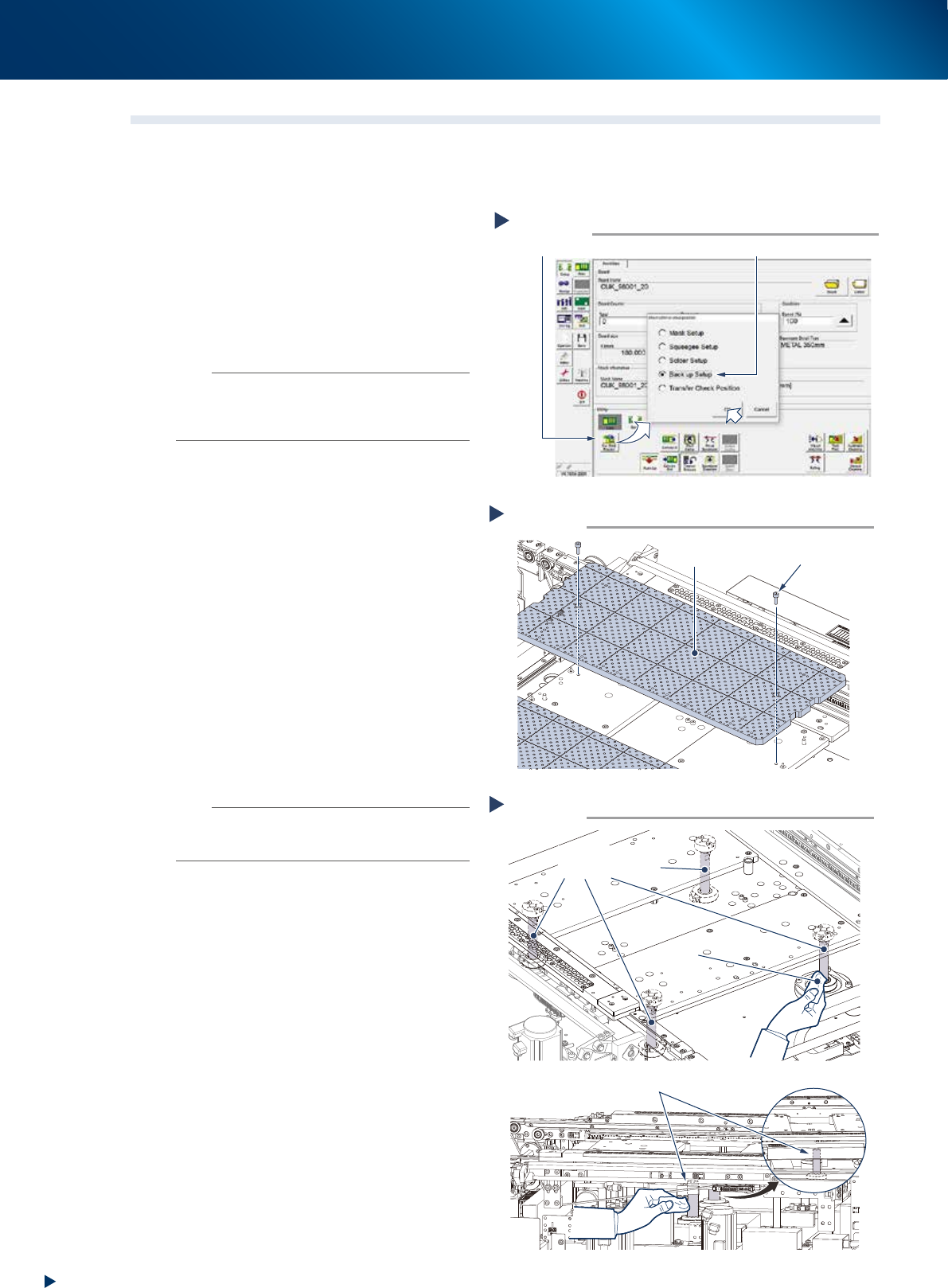
1
Raise the PU-axis.
1. Read any board data.
2. Press the [Change Setup & Move Pos.]
button on the [Setup] tab of the utility
screen.
3. Select "Backup Setup" and press the [OK]
button.
n
NOTE
Upon selecting "Backup Setup", the conveyor width is
changed maximum, then the pushup plate (PU-axis) raises.
Also, the squeegee unit and cleaning unit move to
machine rear side.
2
Remove the backup pins.
e
1. Press the emergency stop button to open the
safety cover and lower door, then pull up
the maintenance door.
2. Remove all the backup pins or the board
support jigs on the matrix plate.
3
Detach the matrix plate.
1. Loosen the mounting bolts (2 bolts per 1
plate) using a hexagon wrench (4mm).
2. Remove the matrix plates (2 pieces, front
and rear).
4
Clean around the PU-axis.
Wipe away the grease and soiling from the
PU-axis ball screws (4 positions) and the shaft
guides (2 positions) through the side of the
table with lint-free cloth.
n
NOTE
Carefully wipe the lead grooves and the guide grooves of
the ball screw. Additionally, make sure that any dirt is not
remained.
5
Lubricate the shaft guide by applying
the prescribed grease (NSL) on its
surface by hand.
Detaching matrix plate
Step 3
Matrix plate
Mounting bolt
53333-KMJ-10
Cleaning the PU-axis
Step 5
Lint-free cloth
A view from rear side
PU-axis shaft guide
PU-axis
ball screws
53334-KMJ-00
Raising PU-axis
Step 1
Select “Backup Setup”
[Sw. Prod. Position] button
54331-KMJ-00
3. 3-month maintenance
3-25
Chapter 3 Periodic maintenance items
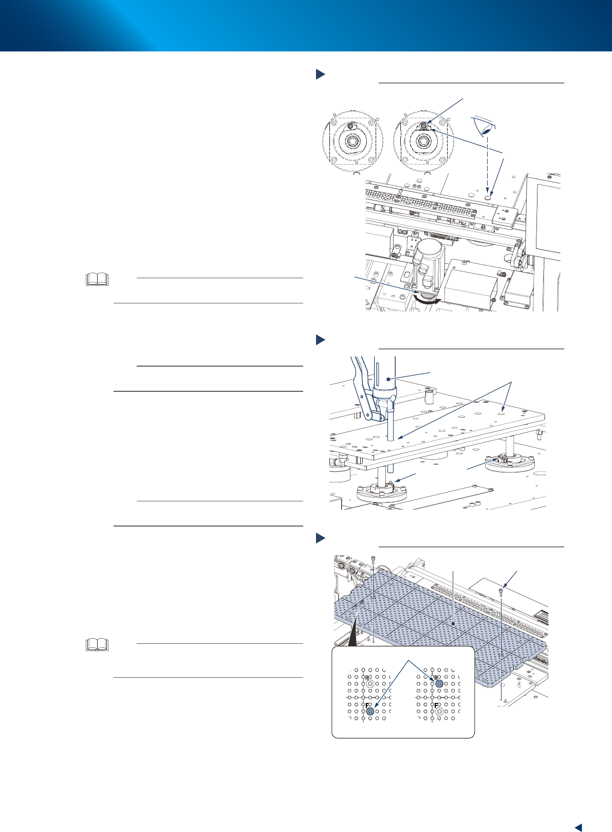
6
Align the grease nipple position of ball
screws.
1. Press the [Units] - [Axis Move] button and
select [PU] tab.
2. Press the [Blake] button to release the
PU-axis blake.
3. The PU-axis ball screw nut rotates as rotating
the pulley unit illustrated at right. Rotate the
pulley unit to align the grease gun insertion
holes and grease nipples.
7
Lubricate the ball screws.
Using a grease gun (standard, 10mm type),
inject the prescribed grease (NSL) from the
grease gun insertion holes to the grease nipples
of ball screws, until the grease seep out from
the gap between ball screw and ball nut.
TIP
When the grease gun cannot reach, rotate the pulley unit
more and lower the pushup plate.
8
Lubricate all the grease nipples.
Repeat the procedures of Step7 to inject grease
to the rest 3 nipples (a total of 4).
n
NOTE
When one grease nipple position is aligned, also the
other three nipples could be aligned.
9
Wipe away excess grease.
Use a lint-free cleaning cloth to wipe away
excess grease from the 4 PU-axis ball screws
through the side of the table.
0
Reattach the matrix plates (front/rear)
by tightening the mounting bolts.
n
NOTE
Matrix plates have a bolt at the position which is written
"F(FRONT)/R(REAR)" to prevent the misplacement.
q
Spread the grease.
1. Return the maintenance door to its original
position, and close the safety cover and the
lower door. Then cancel the emergency
stop.
2. Press the [Pushup] button on [Unit] -
[Conveyor] screen several times to move the
PU-axis up and down.
TIP
The entry screen of board thickness appears upon raising
PU-axis. Press the [OK] button as it is to raise PU-axis if the
displayed thickness is 1 to 2 mm.
Aligning the grease nipple positions
Step 6
Looking from above
Checking for the grease nipple position
Shifted Aligned
Pulley
Grease gun
insertion hole
Grease nipple
53335-KMJ-00
Lubricating PU-axis ball screws
Step 7
Grease gun
insertion hole
Grease gun
(standard type nozzle)
Grease nipples
53336-KMJ-00
Attaching matrix plate
Step 10
Matrix plate
Mounting bolt
Plate/front side
Plate/rear side
Misplacement prevention bolt
53386-KMJ-00