YSP10_Mainte_E.pdf - 第102页
4. Mask vacuum unit 4-13 Chapter 4 The parts to be replaced and its procedures 4. Mask vacuum unit This section describes the procedur es for cleaning and replacing the mask vacuum filter of YSP10. 4.1 Cleaning and r epl…
3. Conveyor transfer belt
4-12
Chapter 4 The parts to be replaced and its procedures
0
Check the belt assembly condition.
1. Close machine safety cover and lower
maintenance cover. Then close lower door
and cancel the emergency stop.
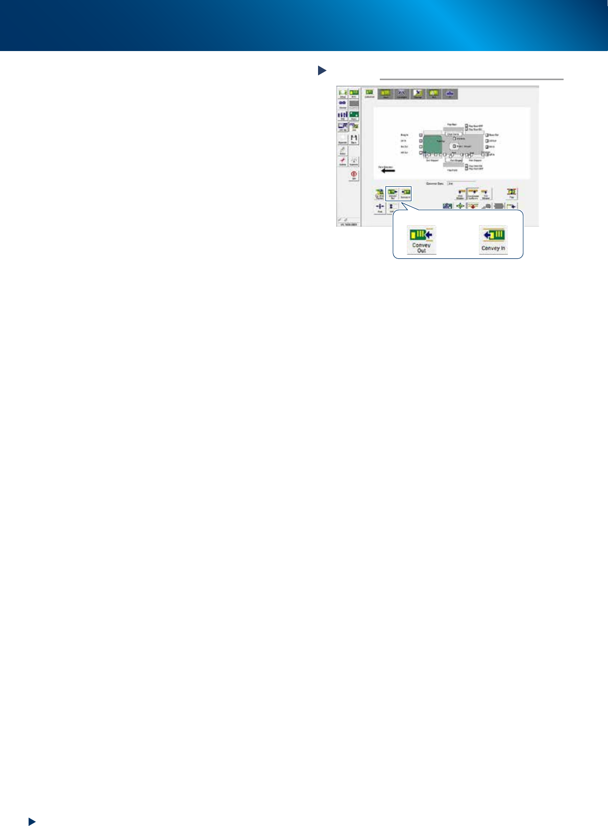
2. Press again the [Cleaner Connect] button on
[Unit] - [Cleaner] screen.
The cleaning unit moves to its original
position (machine front side) and disconnects
with the camera unit.
3. Press the [Convey In] or [Convey Out] button
on [Unit] - [Conveyor] screen to transfer
several boards, and check the motion.
4. Rotate the conveyor belt by hand and
confirm that no slack or unevenness of
rotation is found.
When any slack or unevenness of rotation is
found, check the belt assembly condition,
and readjust the position of pulley bracket
(or pulley).
Checking the transfer motion
Step 10
[Convey Out] button [Convey In] button
54401-KMJ-00
4. Mask vacuum unit
4-13
Chapter 4 The parts to be replaced and its procedures
4. Mask vacuum unit
This section describes the procedures for cleaning and replacing the mask vacuum filter of YSP10.
4.1 Cleaning and replacing the mask vacuum filter
e
1
Open the lower door.
1. Press the emergency stop button to open the
safety cover.
2. Open the lower door.
2
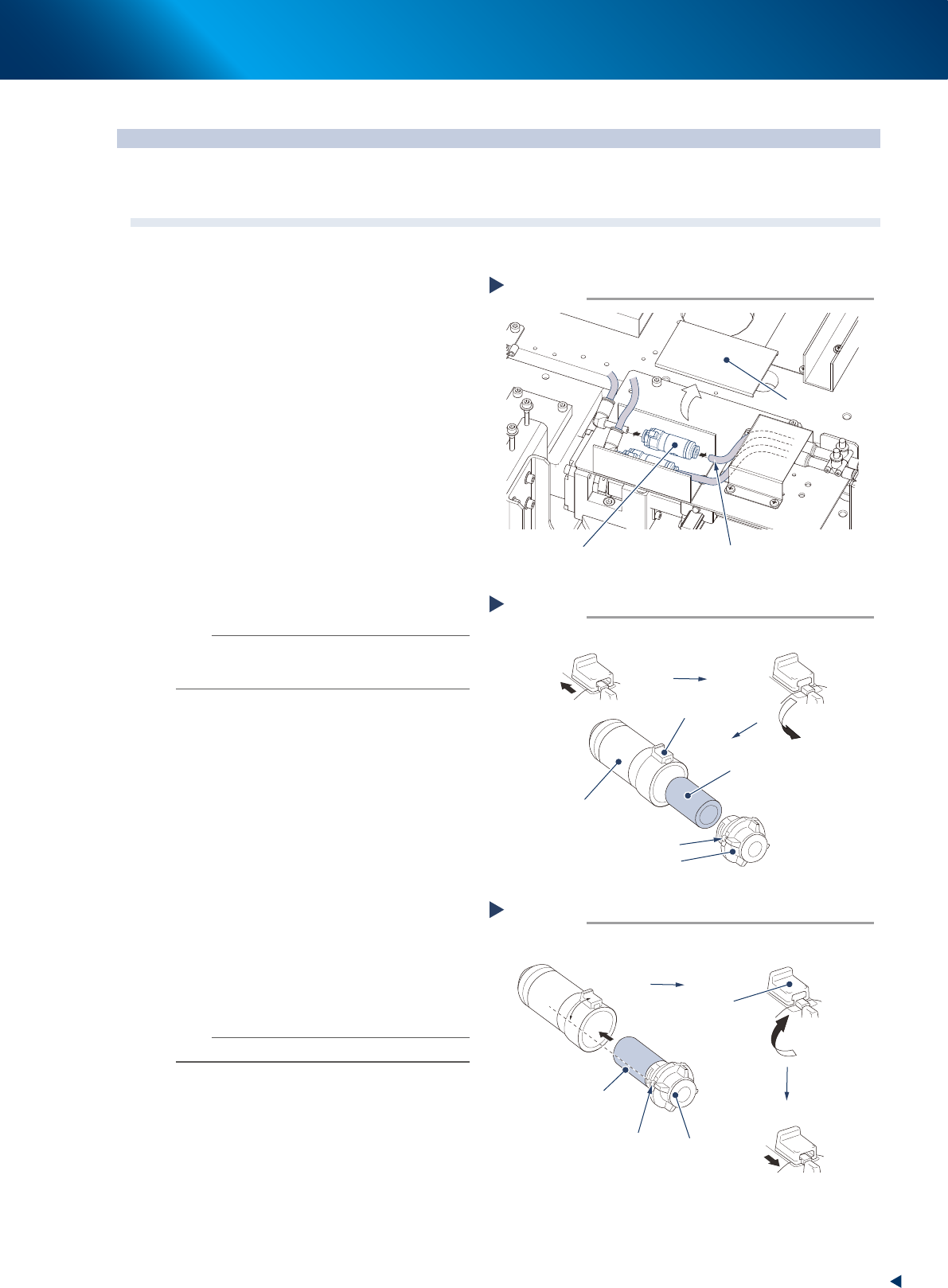
Remove the lter unit by detaching the
duct cover and pulling out the air hose
from the lter unit.
3
Take out the lter from the lter unit.
1. Slide the rotation stopper to arrow direction
to unlock.
2. Rotate the cover to counterclockwise 90
degrees or more.
3. Pull out the cover from the case to take out
the filter element.
4
Blow to clean the taken out lter inside
and outside with air blow tool.
n
NOTE
If dust cannot be removed or the filter has worn out,
replace the filter with a new one (KGR-M4995-F0X,
FILTER, SPACE).
5
Attach the lter to lter unit.
1. Attach the cleaned or new filter to the cap
to insert into the case.
2. Align the projection of the cover to the
position from 45 degrees counterclockwise
of the rotation stopper, and insert it until it
touches to the bottom.
3. Rotate the cap clockwise to align with the
rotating stopper.
4. Return the rotation stopper to the locked
position, and make sure that the cover is
firmly locked.
6
Reattach the lter unit.
1. Attach the joints on both sides of filter unit
to the air hose.
2. Return the duct cover to its original position.
n
NOTE
Attach the filter unit with care of its direction.
Removing the filter unit
Step 2
Filter unit
Air hose
Duct cover
53381-KMJ-00
Taking out the filter
Step 3
Filter
Cap
Projection of cap
Slide the rotation stopper
Case
Rotation stopper
Rotate the stopper 90 degrees or more
53438-KMJ-00
Attaching the filter
Step 5
Cap
Projection of cap
45°
Rotate to the rotation stopper
Insert the filter
Filter inserted into the cap
Rotation
stopper
Lock the cap
53439-KMJ-00

Chapter 5 Lubrication points and schedule
Contents
1. Lubrication tools and grease 5-1
1.1 Compatible grease 5-1
1.2 Grease gun 5-1
2. Lubrication points 5-2
2.1 Printing head unit 5-2
2.1.1 SY-axis 5-2
2.1.2 SZ-axis 5-3
2.2 Conveyor unit 5-4
2.2.1 W1-axis, W2-axis, W3-axis (conveyor auto width) 5-4
2.3 Table unit 5-5
2.3.1 X1-axis and X2-axis 5-5
2.3.2 Y-axis 5-6
2.3.3 Z-axis 5-7
2.3.4 PU-axis 5-8
2.4 Recognition unit 5-9
2.4.1 CX-axis 5-9
2.4.2 CY1-axis and CY2-axis 5-10
2.5 Other lubrication points 5-11
2.5.1 Cleaning unit 5-11
2.5.2 Suction unit 5-12