00197454-01_AI_Portal_40mm_TwinVHF_SX12_de_en.pdf - 第100页
assembly Preparations at the Machine 3.1.3 Removing the End Position Buffer 100 Reconfiguration Kit Twin VHF with Gantry Reconfiguration Ki t T w i n V H F m i t P o r - 3.1.3 3 . 1 . 3 R e m o v in g t h e E n d P o s i…
assembly
3.1.1 Removing the Gantry Preparations at the Machine
Reconfiguration Kit Twin VHF with Gantry Reconfiguration Kit Twin VHF mit Portal 99
3
3 assembly
$ssembly
3.1
3.1 Preparations at the Machine
Preparations at the Machine
See also
1.2 Preparatory Work... [ ➙ 76]
3.1.1
3.1.1 Removing the Gantry
Removing the Gantry
► I you need to remove an existing gantry before installation, read the assembly instructions "Gantry
Modularity SX1/SX2" [00196626-xx] (English/German).
3.1.2
3.1.2 Opening the Covers
Opening the Covers
► Switch off the machine, disconnect it from the power supply and secure it to prevent unauthorized
reactivation. Observe the instructions in section "1.2 Preparatory Work..." [ ➙ 76].
NOTICE
Description example
This manual describes the upgrading of gantry 2 at location 2. The assembly of gantry 1 is the
same. The diagrams sometimes show standard gantries as an example. You should still per
-
form the tasks described. Any differences will be explicitly indicated.
NOTICE
Mapping
When upgrading gantry 1 (master gantry) at location 1, component board mapping must be per
-
formed after the assembly.
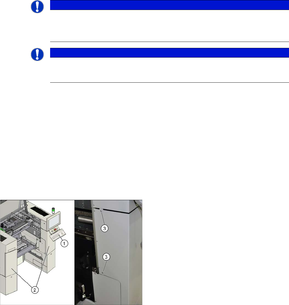
► Open the protective cover and move the component
trolley out of the machine.
► Remove the keyboard (1).
► Loosen the two screws (3) fastening the side covers
(2) on the right and left.
► Open the two covers (2).
assembly
Preparations at the Machine 3.1.3 Removing the End Position Buffer
100 Reconfiguration Kit Twin VHF with Gantry Reconfiguration Kit Twin VHF mit Por
-
3.1.3
3.1.3 Removing the End Position Buffer
Removing the End Position Buffer
The long end position buffers must be fitted in SIPLACE SX1 machines with one gantry. When convert
-
ing an SX1 to an SX2, you need to remove this and replace it with short end position buffers.
3.1.4
3.1.4 Preparing the Trailing Cable
Preparing the Trailing Cable
Overview
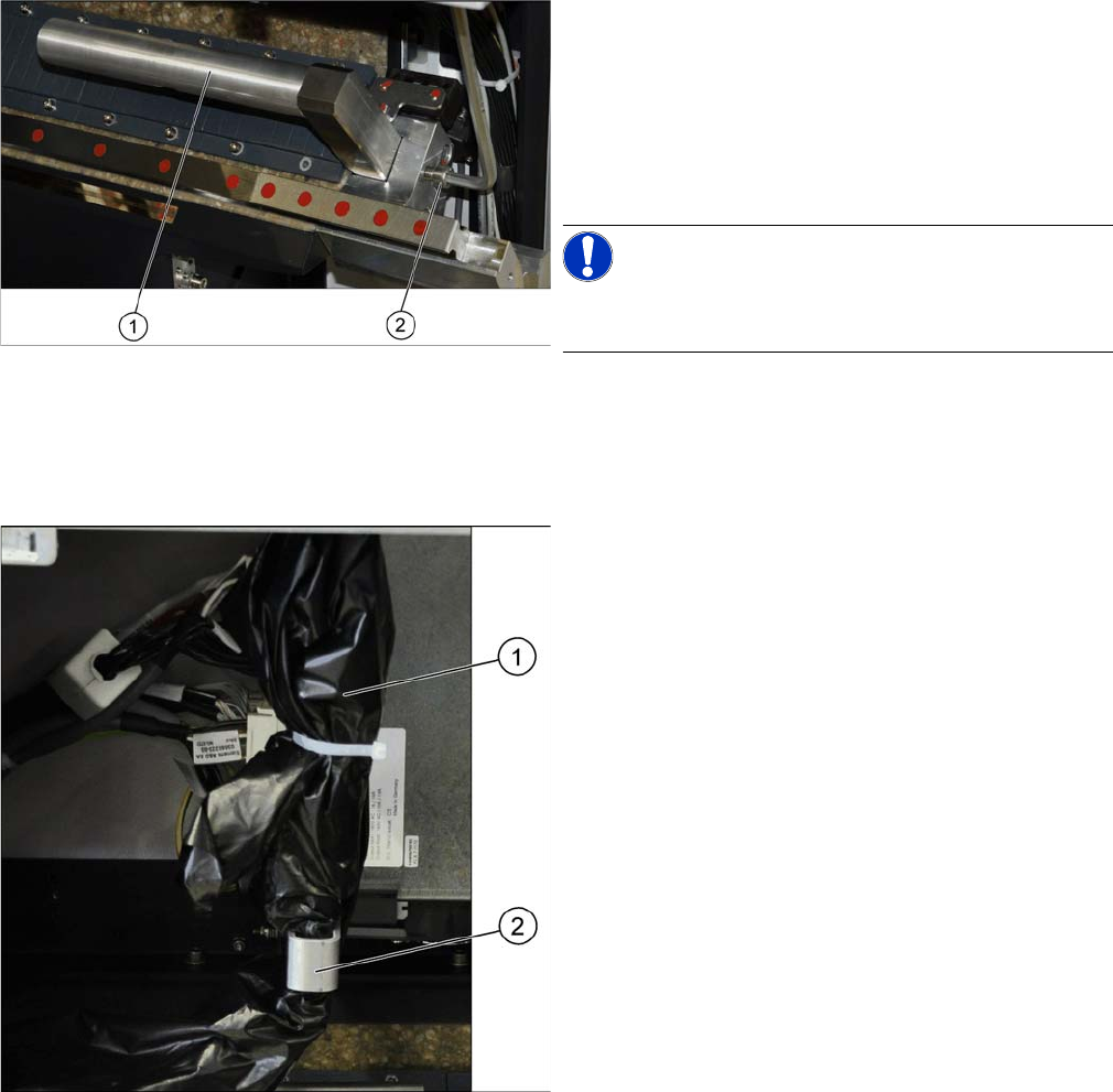
Remove the two long end position buffers. After fitting the
second gantry, fit the two short end position buffers in
place of the long ones.
► Loosen the fastening screw (2) on the long end posi
-
tion buffer (1).
► Remove the two end position buffers from the right
and left sides.
NOTICE!
Keep the two long end position buffers in the "Prepared"
case for fitting back into place later on.
The trailing cable (1) is packed in black plastic foil and
fixed to a holder (2).
assembly
3.1.5 Fitting the Stationary Camera Preparations at the Machine
Reconfiguration Kit Twin VHF with Gantry Reconfiguration Kit Twin VHF mit Portal 101
Loosening the trailing cable
3.1.5
3.1.5 Fitting the Stationary Camera
Fitting the Stationary Camera
If not already present, you will need to fit a stationary camera.
► Refer to the appropriate assembly instructions:
▪ Assembly instructions stationary camera type 25 (FC) [DE+EN: 00194554-xx]
▪ Assembly instructions stationary camera type 33/36 (C) [DE+EN: 00196608-xx]
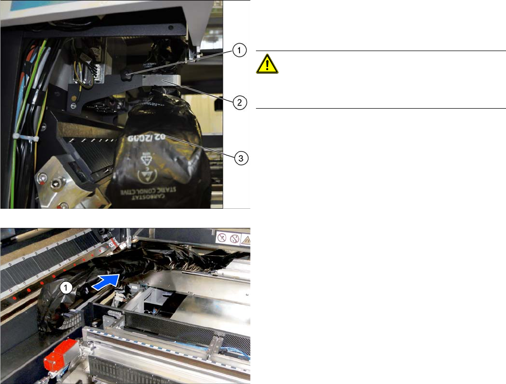
► Loose the fixture screw (1) on the holder (2).
► Carefully disconnect the trailing cable (3) from its
holder.
CAUTION!
Take care when handling the trailing cable!
Take care not to damage the foil or the trailing cable.
► Place the holder and the fixture screw in the "Pre
-
pared case" for fitting back into place later on.
► Take the trailing cable (1) and place it carefully to
-
wards the front, into the machine.