00197454-01_AI_Portal_40mm_TwinVHF_SX12_de_en.pdf - 第121页
assembly 3.7.4 Note GCU Final Work Reconfiguration Kit Twin VHF with Gantry Re configuration Kit Twin VHF mit Portal 121 3.7.4 3 . 7 . 4 N o t e G C U Note GCU Power cable GCU 3 [03068 134-xx] ► Please check the connecti…

assembly
Final Work 3.7.3 Checking the Gantry Coding
120 Reconfiguration Kit Twin VHF with Gantry Reconfiguration Kit Twin VHF mit Por
-
3.7.3
3.7.3 Checking the Gantry Coding
Checking the Gantry Coding
► Check the DIP switch (1) for the gantry coding of the
locations on the head interface.
Switch Designation Gantry 1 Gantry 2
1 DC/DC OFF OFF
2FANOFFOFF
3P1OFFON
4P0OFFOFF
assembly
3.7.4 Note GCU Final Work
Reconfiguration Kit Twin VHF with Gantry Reconfiguration Kit Twin VHF mit Portal 121
3.7.4
3.7.4 Note GCU
Note GCU
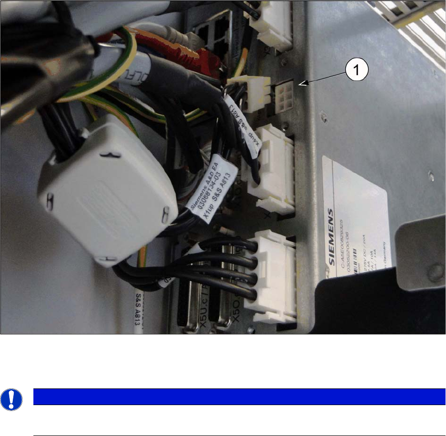
Power cable GCU 3 [03068134-xx]
► Please check the connection of the GCU3 power cable with the connector X1up. (1) to ensure a cor
-
rect start-up of the machine.
NOTICE
Dismantling a Gantry
The connector X1up has to be disconnected from the GCU3, if the gantry is dismantled later on.
assembly
Final Work 3.7.5 Checking the Camera Cable
122 Reconfiguration Kit Twin VHF with Gantry Reconfiguration Kit Twin VHF mit Por
-
3.7.5
3.7.5 Checking the Camera Cable
Checking the Camera Cable
► Check whether the camera cable is connected to the hotlink card on the box PC. Make sure that the
connections are correct. (See labelling on hotlink card).
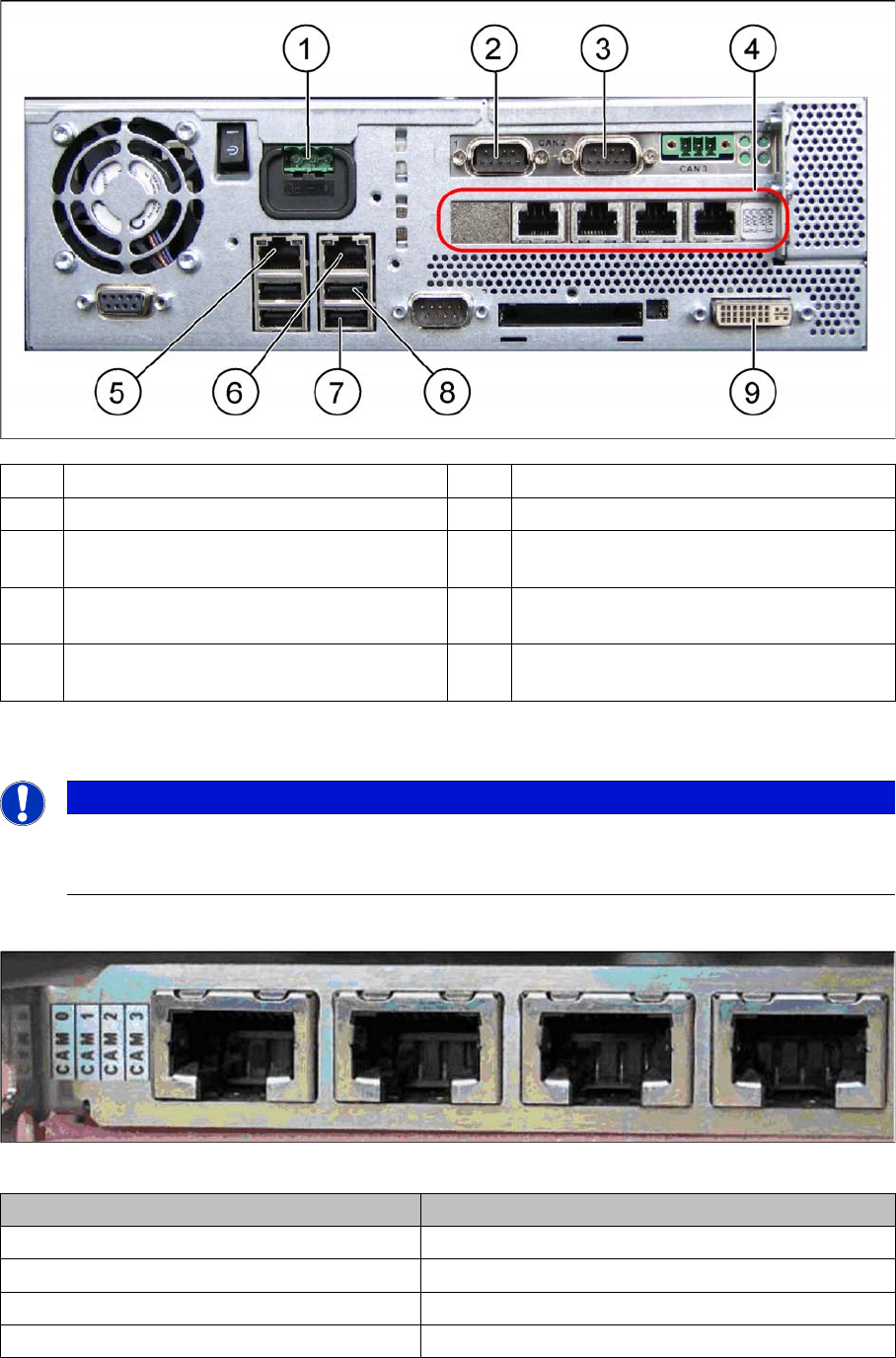
Hotlink card [03032343-xx]
Hotlink card [03032343-xx]
(1) Power supply DC 24 V (2) CAN 1 on the CAN bus card
(3) CAN 2 on the CAN bus card (4) Hotlink card
(5) LAN 2 – connection to Vision computer
(optional second BoxPC)
(6) LAN 1 – connection to SIPLACE Pro
(connection to line hub)
(7) USB 0 – connection for keyboard/touch
-
screen (connection to USB hub)
(8) USB 2 – connection for an external DVD
drive
(9) DVI/VGA monitor connection
(connection to video multiplexer)
NOTICE
Hotlink card:
Pay attention to the connections of the different hotlink cards, recognizable due to the sticker
(see the following explanation)!
Connection on the hotlink card Designation
CAM0 Head cameras gantry 1
CAM1 Head cameras gantry 2
CAM2 Stationary cameras gantry 1
CAM3 Stationary cameras gantry 2