00197454-01_AI_Portal_40mm_TwinVHF_SX12_de_en.pdf - 第125页
assembly 3.7.7 Performing Calibration Final Work Reconfiguration Kit Twin VHF with Gantry Re configuration Kit Twin VHF mit Portal 125 Calibration ► SR 704.xx ► User => Service ► Machine Service => Machine Configur…
assembly
Final Work 3.7.7 Performing Calibration
124 Reconfiguration Kit Twin VHF with Gantry Reconfiguration Kit Twin VHF mit Por
-
3.7.7
3.7.7 Performing Calibration
Performing Calibration
Overview
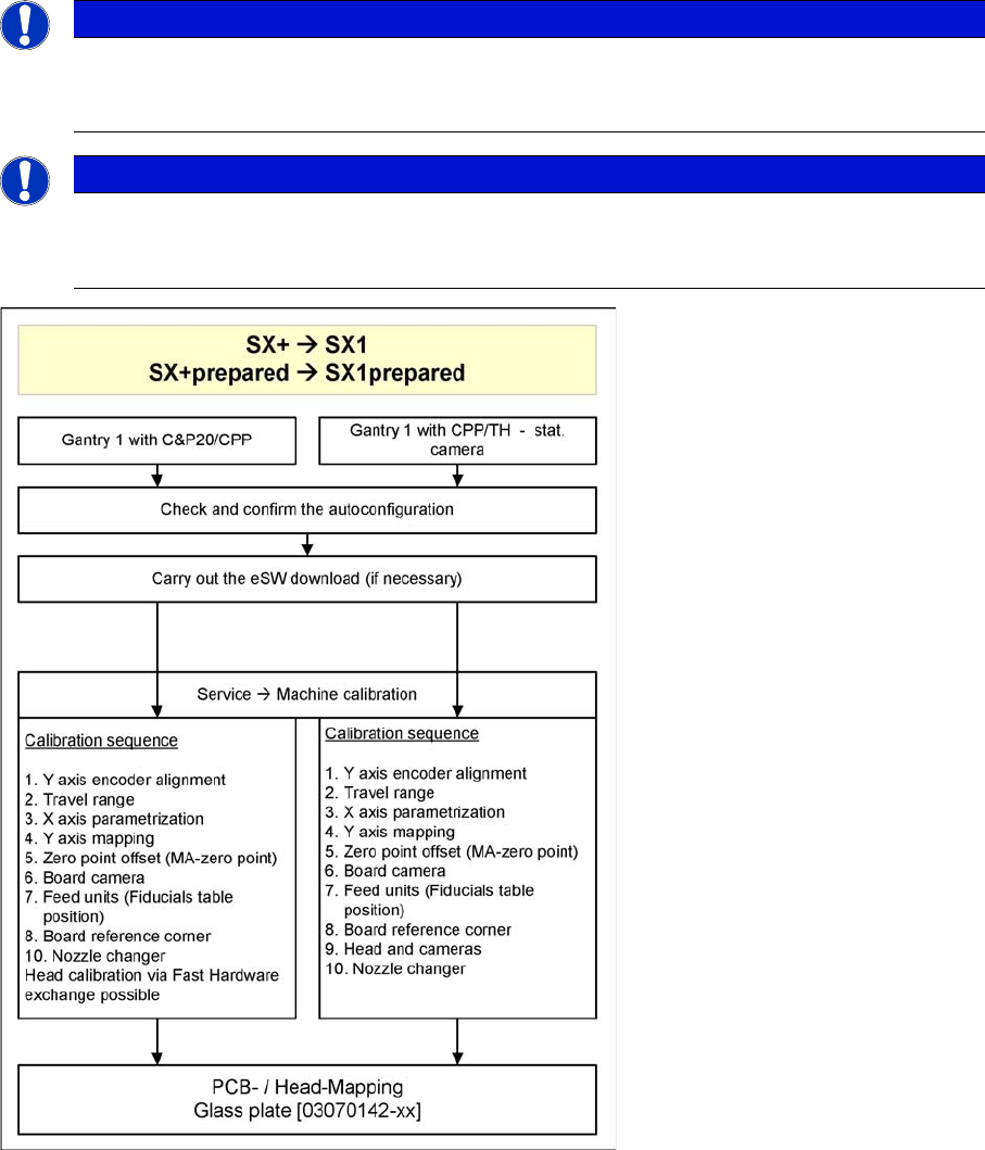
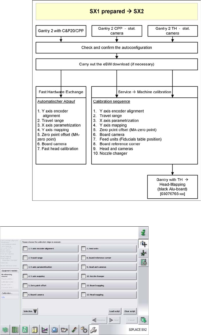
The SW704 divides the mapping data and then merges them during the gantry upgrade. In most cases
this means that only a brief calibration procedure needs to be performed (see Fast Hardware Exchange
and flow diagram).
If gantry 1 is fitted, you need to perform PCB/component mapping with the glass plate, irrespective of
the head configuration (gantry 1 is the master gantry).
NOTICE
TH gantry at location 2
If there is a TH gantry at location 2 (gantry 2), the PCB mapping data must be present. Com
-
ponent mapping can then be performed using the aluminum plate.
NOTICE
Long Board Option
If a gantry is installed on a machine with Long Board Option (LBO), this gantry has to be
mapped using the "Mapping with LBO" button.
assembly
3.7.7 Performing Calibration Final Work
Reconfiguration Kit Twin VHF with Gantry Reconfiguration Kit Twin VHF mit Portal 125
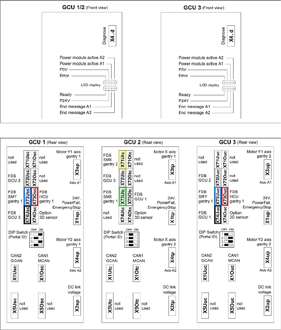
Calibration
► SR 704.xx
► User => Service
► Machine Service => Machine Configuration
► Confirm and Change Configuration => confirm
assembly
Final Work 3.7.7 Performing Calibration
126 Reconfiguration Kit Twin VHF with Gantry Reconfiguration Kit Twin VHF mit Por
-
3.7.7.1
3.7.7.1 Description and Connections on the GCU
Description and Connections on the GCU
GCU - front side
GCU - rear side