00197454-01_AI_Portal_40mm_TwinVHF_SX12_de_en.pdf - 第72页
Anhang Auszüge aus der Serviceanleitung 4.1.3 Kopfadapter HCU und HCU t auschen 72 Reconfiguration Kit Twin VHF with Gantry Reconfiguration Kit Twin VHF mit Por -
Anhang
4.1.3 Kopfadapter HCU und HCU tauschen Auszüge aus der Serviceanleitung
Reconfiguration Kit Twin VHF with Gantry Reconfiguration Kit Twin VHF mit Portal 71
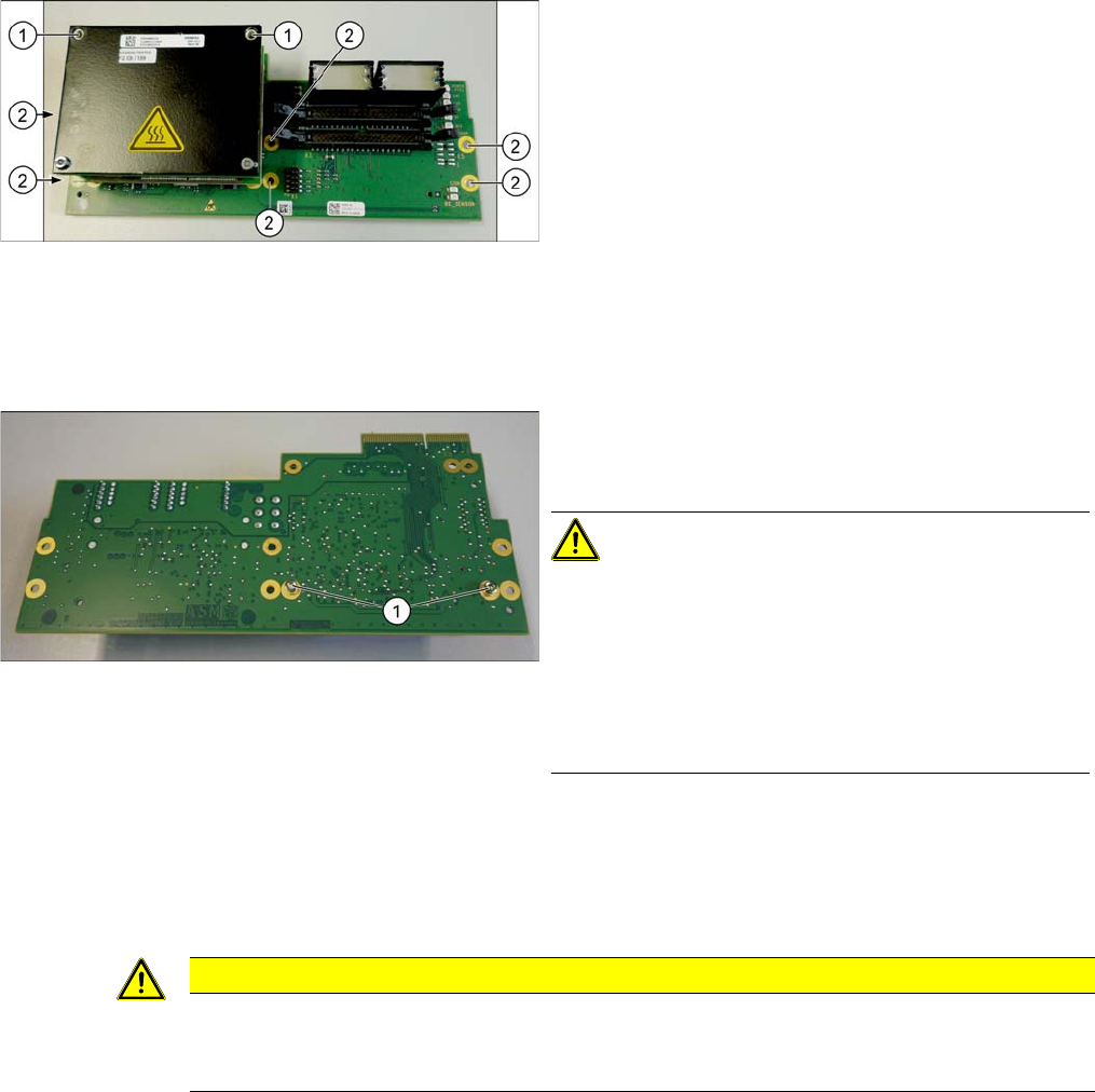
HCU umbauen
Sollten Sie nur den Basisadapter ohne HCU(s) bestellt haben, so müssen Sie die HCU(s) umbauen. Ge
-
hen Sie dazu wie folgt vor:
► Wiederholen Sie den Vorgang ggf. für die zweite HCU (nur bei Twin).
Einbau
► Verfahren Sie für den Einbau in umgekehrter Reihenfolge. Beachten Sie dabei folgende Hinweise:
► Lösen Sie alle Befestigungsschrauben (2) der Plati
-
ne.
► Zusätzlich ist die Platine mit den jeweils oberen bei
-
den Schraube (1) der HCUs befestigt. Lösen Sie die
-
se ebenfalls.
► Ziehen Sie die Platine vorsichtig nach unten ab.
Beachten Sie dabei, dass die Kopfadapterplatine von
unten über eine Steckverbindung mit dem Kopf-Inter
-
face verbunden ist.
► Lösen Sie dazu die beiden Befestigungsschrauben
der HCU auf der Platinenrückseite und ziehen Sie die
HCU vorsichtig vom Basisadapter.
VORSICHT!
Beilagscheiben und Stiftleiste
Achten Sie darauf die Beilagscheiben nicht zu verlieren.
Vermerken Sie sich ggf. die Menge der Scheiben pro
Schraube, da die Anzahl unterschiedlich sein kann. Die
-
se müssen genauso wieder eingebaut werden.
Achten Sie darauf die unter der HCU liegende Stiftleiste
nicht beschädigen.
VORSICHT
Einbauhinweise
► Überprüfen Sie die Firmware und führen Sie ggf. einen Download durch (siehe Servicean
-
leitung).
Anhang
Auszüge aus der Serviceanleitung 4.1.3 Kopfadapter HCU und HCU tauschen
72 Reconfiguration Kit Twin VHF with Gantry Reconfiguration Kit Twin VHF mit Por
-

Introduction
1.1.1 Conventions for the use of safety instructions Safety Instructions
Reconfiguration Kit Twin VHF with Gantry Reconfiguration Kit Twin VHF mit Portal 73
1
1 Introduction
Introduction
This guide describes the installation of the "Reconfiguration Kit Twin VHF with Gantry" for 40 mm com
-
ponents on SIPLACE® SX1/SX2 V2 machines.
1.1
1.1 Safety Instructions
Safety Instructions
1.1.1
1.1.1 Conventions for the use of safety instructions
Conventions for the use of safety instructions
This manual contains notes that must be observed to guarantee your personal safety and to avoid dam
-
age to equipment. These notes are highlighted by warning triangles and are indicated as follows accord
-
ing to the level of risk:
DANGER
Nonobservance of these safety instructions may cause injury to personnel and damage to the
machine!
► Please observe the safety instructions in the user manual of the relevant machine for all
work!
DANGER
Definition
For the purposes of this manual, this indicates that fatal or severe injuries or considerable dam
-
age to property will occur if this hazard warning is not observed.
WARNING
Definition
For the purposes of this manual, this indicates that fatal or severe injuries or considerable dam
-
age to equipment may occur if these warning instructions are not followed.
CAUTION
Definition
For the purposes of this manual, this indicates that minor injuries or damage to property may
occur if this caution is not observed.
NOTICE
Definition
For the purposes of this manual, this note provides information about the product or indicates
a part of the manual that requires particular attention.