00197454-01_AI_Portal_40mm_TwinVHF_SX12_de_en.pdf - 第113页
assembly 3.2.5 Fitting the HCUs and HCU Base Adapter Fitting the Gantry Reconfiguration Kit Twin VHF with Gantry Re configuration Kit Twin VHF mit Portal 113 Remove the tilt guard and move in the gantry The docking hooks…
assembly
Fitting the Gantry 3.2.5 Fitting the HCUs and HCU Base Adapter
112 Reconfiguration Kit Twin VHF with Gantry Reconfiguration Kit Twin VHF mit Por
-
3.5
3.5 Fitting the Gantry
Fitting the Gantry
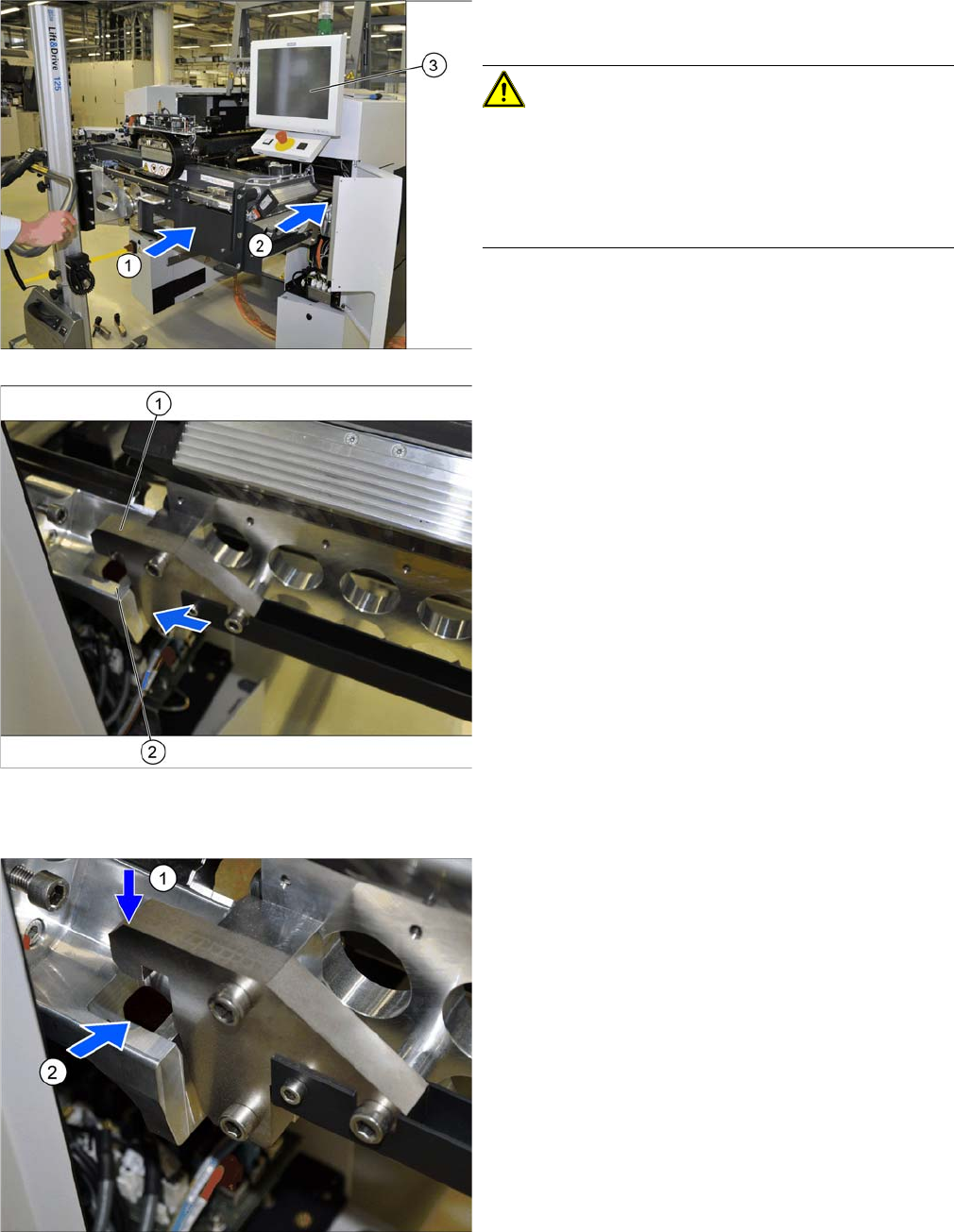
Hooking the gantry carrier into place on the machine
► (1) Use the gantry lift to move the gantry in front of the
machine location.
CAUTION!
Move the gantry carefully
Make sure that you do not damage the monitor (3).
Make sure that you do not hit the gantry anywhere and do
not move it too far into the machine (2). Always check the
right and left sides.
1. Docking hook on the gantry carrier
2. Docking unit on the machine linear guides
► Move the gantry forwards so that the gantry carrier
docking hooks (1) are in front of the machine docking
unit (2).
► Always check the right and left sides.
► Lift the gantry so that the gantry carrier docking hooks
(1) are above the machine docking unit (2).
► Carefully lower the gantry so that the two docking
hooks (1) slide reliably into the openings in the dock
-
ing unit (2).
► Always check the right and left sides.
assembly
3.2.5 Fitting the HCUs and HCU Base Adapter Fitting the Gantry
Reconfiguration Kit Twin VHF with Gantry Reconfiguration Kit Twin VHF mit Portal 113
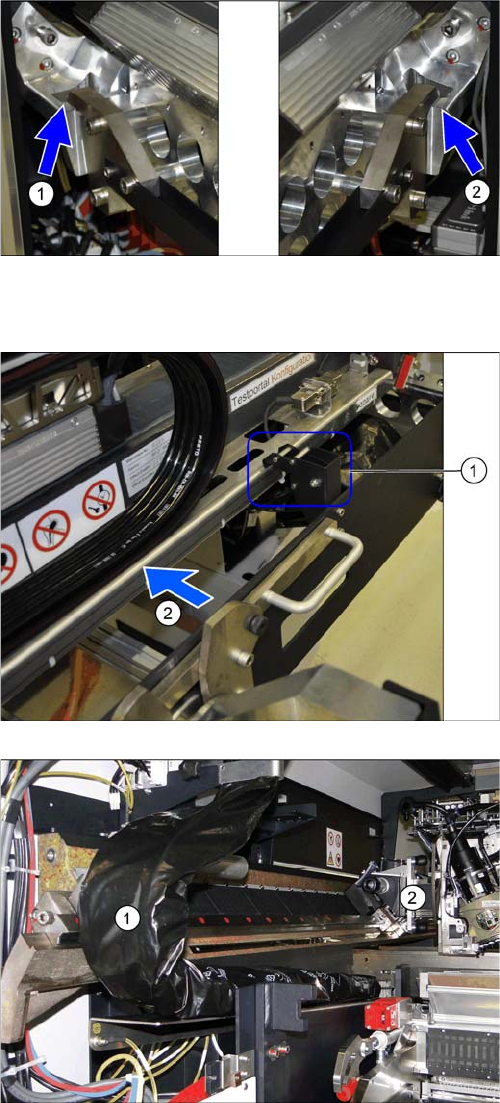
Remove the tilt guard and move in the gantry
The docking hooks are hooked into place on the left (1)
and right (2) sides.
The gantry carrier with the gantry is now fixed reliably
onto the machine.
► Open the tilt guard (1).
► Push the gantry (2) into the machine so that both
sides of the gantry rest on the two linear guides.
► Move the gantry lift with the gantry carrier out of the
location.
► Move the gantry (2) into the machine so that the trail
-
ing cable (1) can be pulled underneath, through the
gantry.
assembly
Fitting the Gantry 3.5.1 Replacing/Fitting the End Position Buffers
114 Reconfiguration Kit Twin VHF with Gantry Reconfiguration Kit Twin VHF mit Por
-
3.5.1
3.5.1 Replacing/Fitting the End Position Buffers
Replacing/Fitting the End Position Buffers
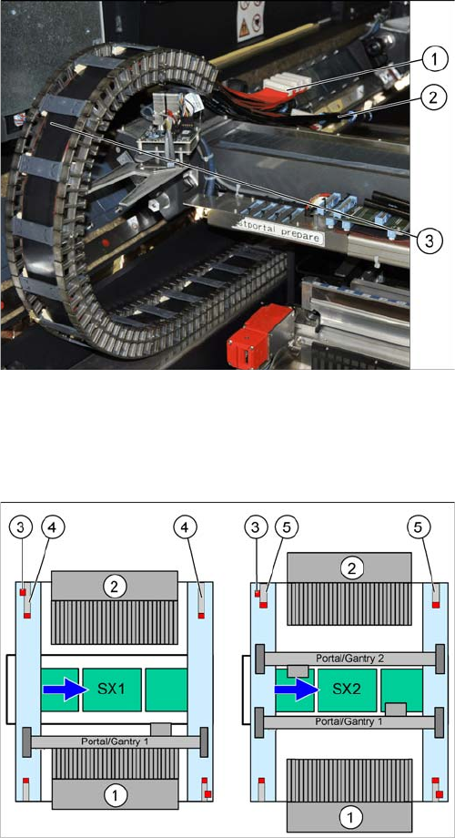
Overview
► Carefully place the flat ribbon cable (1) and the pneu
-
matic connections (2) over the gantry.
► Remove the black plastic foil. A cable tie fixes the
black plastic foil to the trailing cable (1).
When upgrading from an SX1 to an SX2, you need to fit
the short end position buffers at location 2.
When downgrading from an SX2 to an SX1, fit the buffer
with distance pipe at location 2.
When fitting a 40 mm gantry, you need to fit the buffer
with distance pipe at location 2 of the SX1. (Buffer labe
-
ling: "LOC2, VHF SX1")
1. Location 1
2. Location 2
3. Security switch
4. Buffer with distance pipe at an SX1
Standard: 226.5 mm
Twin VHF: 174 mm
5. Short buffer on an SX2 (standard and Twin VHF)