00197454-01_AI_Portal_40mm_TwinVHF_SX12_de_en.pdf - 第82页
Brief Description Overview 2.1.1 Overview of SX1/SX2 V2 82 Reconfiguration Kit Twin VHF with Gantry Reconfiguration Kit Twin VHF mit Por - 2.1 2 . 1 O v e r v ie w Overview 2.1.1 2 . 1 . 1 O v e r v ie w o f S X 1 / S X …
Brief Description
Reconfiguration Kit Twin VHF with Gantry Reconfiguration Kit Twin VHF mit Portal 81
2
2 Brief Description
Brief Description
The Twin VHF option enables you to process 40 mm high components with a maximum placement force
of 70 Nm.
Machine frame
The 40 mm option requires an upgraded machine frame with higher input and output areas.
The option can also be fitted in V2 machines with an old machine frame. However, in this case, the max
-
imum component height is limited to 35 mm.
Gantry
This option requires a new gantry. This is higher than the standard gantries, has a new head plate, a
new PCB camera and a different position for the X-axis incremental encoder. The machine recognizes
the gantry automatically via the head ID of the Twin VHF fitted.
These gantries can only be used with the Twin VHF head. Other heads can not be used with this gantry.
WPC
For feeding in 40 mm components, you need a "WPC5/6 – 45 mm" (40 mm component height and 5 mm
tray height).
Cover.
For the "WPC5/6 – 45 mm", you need to fit a new cover with a space cut for the WPC.
Serial number Feature Twin VHF
Kxxx Conveyor with mechanical standard stoppers
→ No Twin VHF possible!
Not possible
Lxxx Conveyor with laser light barrier
No higher input and output area
Max. component height
35 mm
Mxxx Conveyor with laser light barrier
Higher input and output area for components with a
height of 40 mm.
Max. component height
40 mm
NOTICE
Gantry modularity
For more information about gantry modularity, read the assembly instructions "Gantry Modular
-
ity SX1/SX2" [00196626-xx].
Brief Description
Overview 2.1.1 Overview of SX1/SX2 V2
82 Reconfiguration Kit Twin VHF with Gantry Reconfiguration Kit Twin VHF mit Por
-
2.1
2.1 Overview
Overview
2.1.1
2.1.1 Overview of SX1/SX2 V2
Overview of SX1/SX2 V2
Overview
2.1.1.1
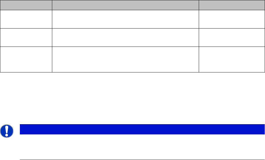
2.1.1.1 Serial Number of Module
Serial Number of Module
1 Sector 1 (pneumatic unit) 2 Sector 2
3 Sector 3 (power supply) 4 Sector 4
5 Location 1 6 Location 2
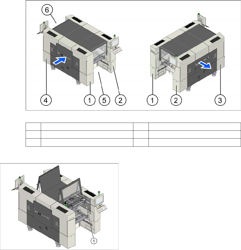
The serial number of your placement machine can be
found on the typeplate (1).
Brief Description
2.1.2 Overview of Twin VHF Head Overview
Reconfiguration Kit Twin VHF with Gantry Reconfiguration Kit Twin VHF mit Portal 83
2.1.2
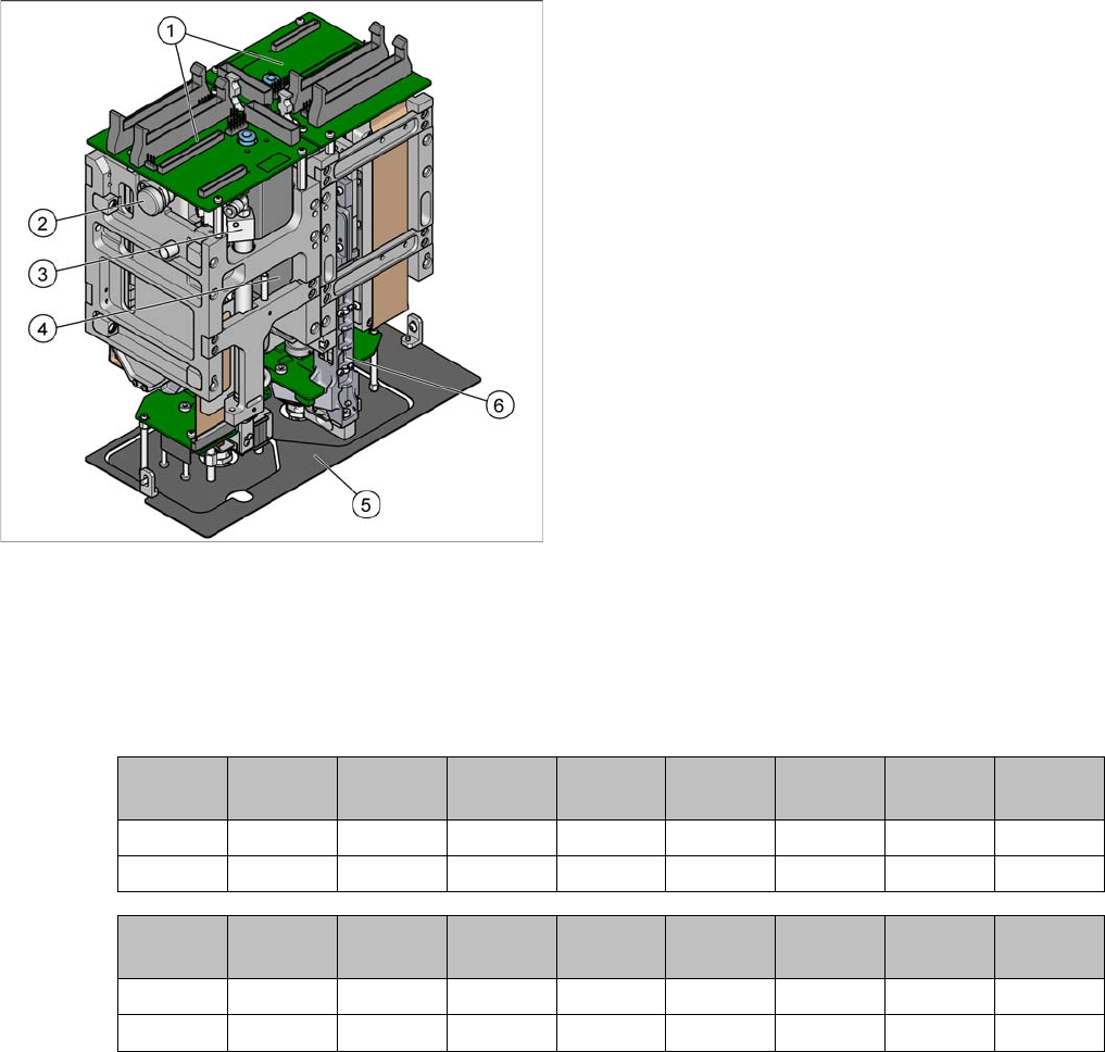
2.1.2 Overview of Twin VHF Head
Overview of Twin VHF Head
2.1.2.1
2.1.2.1 Variants and Use
Variants and Use
The following configurations are possible:
▪ VHF P&P (1 segment, 70 Nm, 30 mm; will be displaced with Twin VHF)
▪ Twin VHF * (2 segments, 70 Nm, 40 mm; scheduled for March 2014)
The placement heads can be used in the following machines:
X = possible
--- = not possible
* = intended
1. Head board
2. Air filter
3. Return unit
4. Digital valve
5. Camera screen [03002232-xx]
6. Z axis
X-Series
(SW60x)
X-Series
(SW70x)
X4i SX1, SX2 DX1, DX2 SX1 V2
SX2 V2
SX4 DX4
VHF P&P --- --- --- --- --- X --- ---
Twin VHF --- --- --- --- --- X --- ---
X2 S * X3 S X4 S X4i S X4 S mi
-
cron *
CA * CA
WLFO *
VHF P&P --- --- --- --- --- --- --- ---
Twin VHF --- --- --- --- --- --- --- ---