00197454-01_AI_Portal_40mm_TwinVHF_SX12_de_en.pdf - 第134页
Appendix Excerpts from the Service Manual 4.1.2 Replacing the PCB Camera [03075363-xx] 134 Reconfiguration Kit Twin VHF with Gantry Reconfiguration Ki t T w i n V H F m i t P o r - 4.1.2 4 . 1 . 2 R e p la c in g t h e P…
Appendix
4.1.1 Installation Positions on the Twin VHF Head Plate Excerpts from the Service Manual
Reconfiguration Kit Twin VHF with Gantry Reconfiguration Kit Twin VHF mit Portal 133
4
4 Appendix
Appendix
4.1
4.1 Excerpts from the Service Manual
Excerpts from the Service Manual
The following chapters are excerpts from the service manual. For more information, refer to the full ser
-
vice manual for your machine.
4.1.1
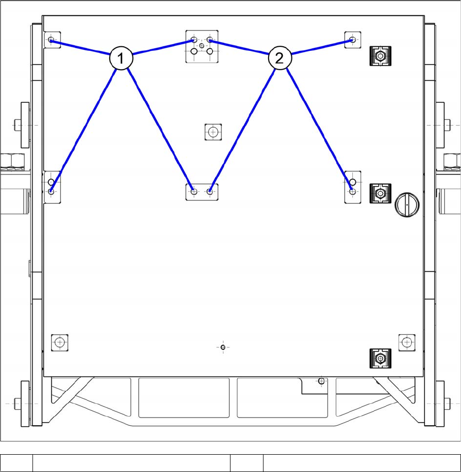
4.1.1 Installation Positions on the Twin VHF Head Plate
Installation Positions on the Twin VHF Head Plate
1 Installation position Twin VHF segment 1 2 Installation position Twin VHF segment 2
Appendix
Excerpts from the Service Manual 4.1.2 Replacing the PCB Camera [03075363-xx]
134 Reconfiguration Kit Twin VHF with Gantry Reconfiguration Kit Twin VHF mit Por
-
4.1.2
4.1.2 Replacing the PCB Camera [03075363-xx]
Replacing the PCB Camera [03075363-xx]
Parts, equipment and tools
▪ PCB camera (TYP34) 28 digital RK [03075363-xx] (standard)
▪ PCB camera (Typ34HU) [03102921-xx] (for Twin VHF on 40mm gantry)
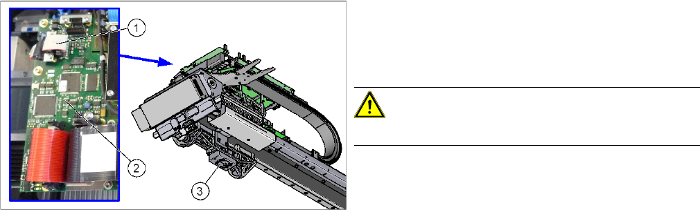
Overview
Removal
► Switch off the machine, disconnect it from the power supply and secure it to prevent unauthorized
reactivation. Observe the instructions in section "1.2 Preparatory Work..." [ ➙ 76].
► Unplug the PCB camera connector on the Vision board spread spectrum.
► Unplug the cable from the assembly plate. Open the corresponding cable ties to help you, if needed.
► Loosen the 4 screws fastening the PCB camera and remove it from the machine.
1. Connection of PCB camera to the Vision board
spread spectrum
2. Vision board spread spectrum
3. PCB camera
CAUTION!
Do not dismantle the PCB camera!
Appendix
4.1.2 Replacing the PCB Camera [03075363-xx] Excerpts from the Service Manual
Reconfiguration Kit Twin VHF with Gantry Reconfiguration Kit Twin VHF mit Portal 135
Installation
► Follow the removal instructions in reverse order for installation. Also observe the following instruc
-
tions:
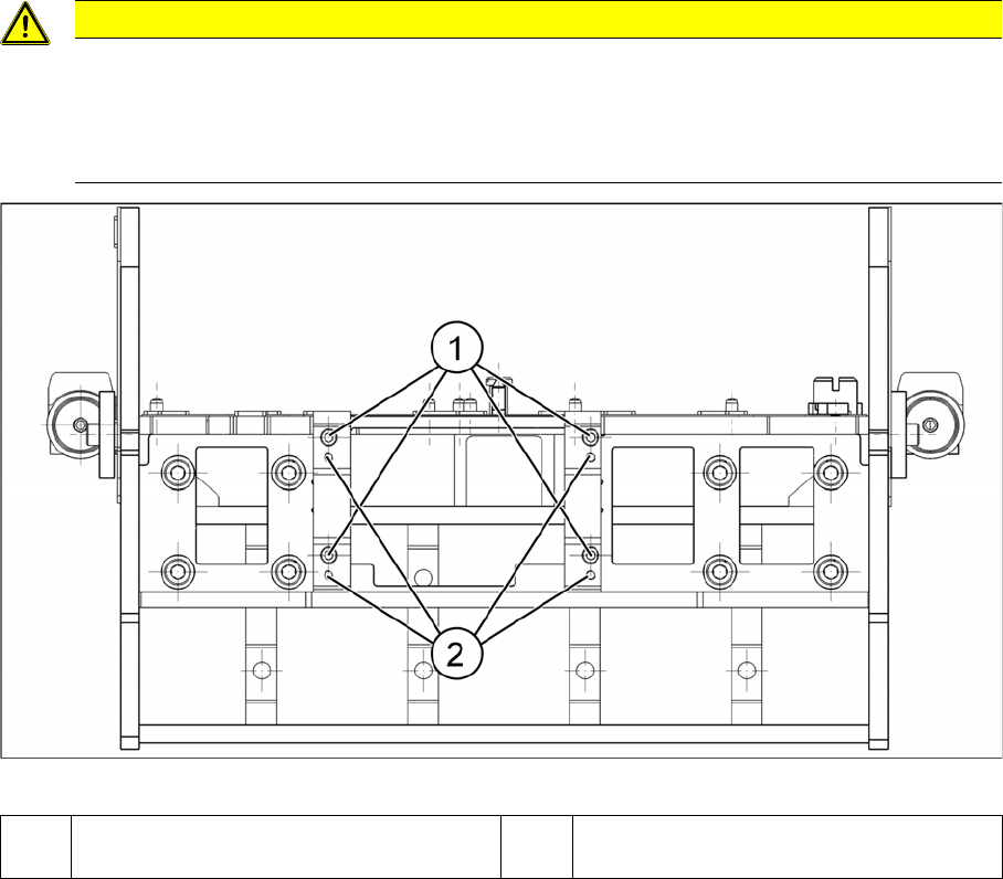
Installation position PCB camera (viewed from below)
CAUTION
Installation instructions
► Make sure you have the correct installation positions (see below)
► Replace any opened cable ties.
► Calibrate the PCB camera, the machine zero point and the head offset.
1 Installation position for C&P and Twin
heads
2 Installation position for DLM heads