00197454-01_AI_Portal_40mm_TwinVHF_SX12_de_en.pdf - 第101页
assembly 3.1.5 Fitting the Stationary Camera Preparations at the Machine Reconfiguration Kit Twin VHF with Gantry Re configuration Kit Twin VHF mit Portal 101 Loosening the trailing cable 3.1.5 3 . 1 . 5 F it t in g t h …
assembly
Preparations at the Machine 3.1.3 Removing the End Position Buffer
100 Reconfiguration Kit Twin VHF with Gantry Reconfiguration Kit Twin VHF mit Por
-
3.1.3
3.1.3 Removing the End Position Buffer
Removing the End Position Buffer
The long end position buffers must be fitted in SIPLACE SX1 machines with one gantry. When convert
-
ing an SX1 to an SX2, you need to remove this and replace it with short end position buffers.
3.1.4
3.1.4 Preparing the Trailing Cable
Preparing the Trailing Cable
Overview
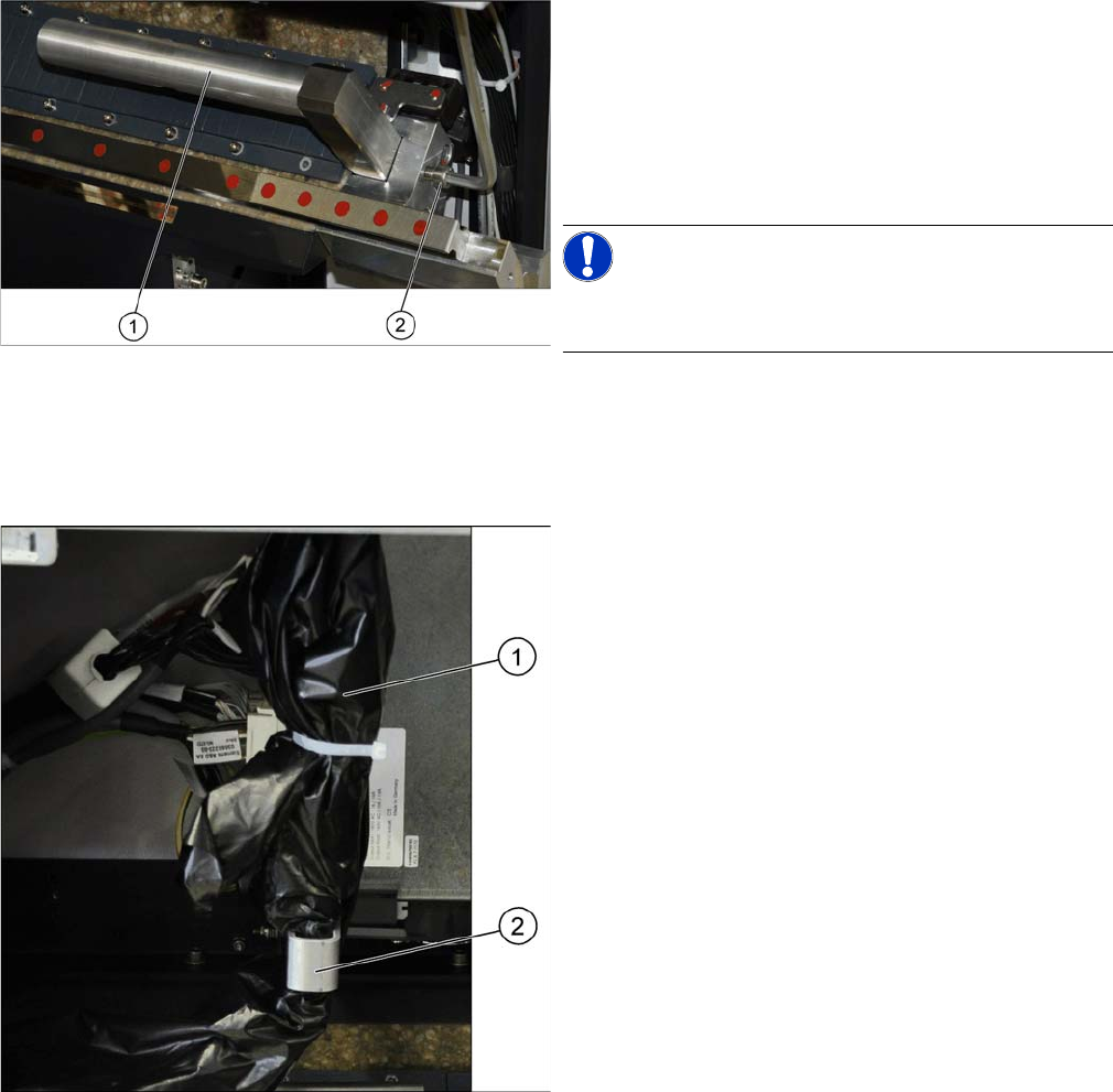
Remove the two long end position buffers. After fitting the
second gantry, fit the two short end position buffers in
place of the long ones.
► Loosen the fastening screw (2) on the long end posi
-
tion buffer (1).
► Remove the two end position buffers from the right
and left sides.
NOTICE!
Keep the two long end position buffers in the "Prepared"
case for fitting back into place later on.
The trailing cable (1) is packed in black plastic foil and
fixed to a holder (2).
assembly
3.1.5 Fitting the Stationary Camera Preparations at the Machine
Reconfiguration Kit Twin VHF with Gantry Reconfiguration Kit Twin VHF mit Portal 101
Loosening the trailing cable
3.1.5
3.1.5 Fitting the Stationary Camera
Fitting the Stationary Camera
If not already present, you will need to fit a stationary camera.
► Refer to the appropriate assembly instructions:
▪ Assembly instructions stationary camera type 25 (FC) [DE+EN: 00194554-xx]
▪ Assembly instructions stationary camera type 33/36 (C) [DE+EN: 00196608-xx]
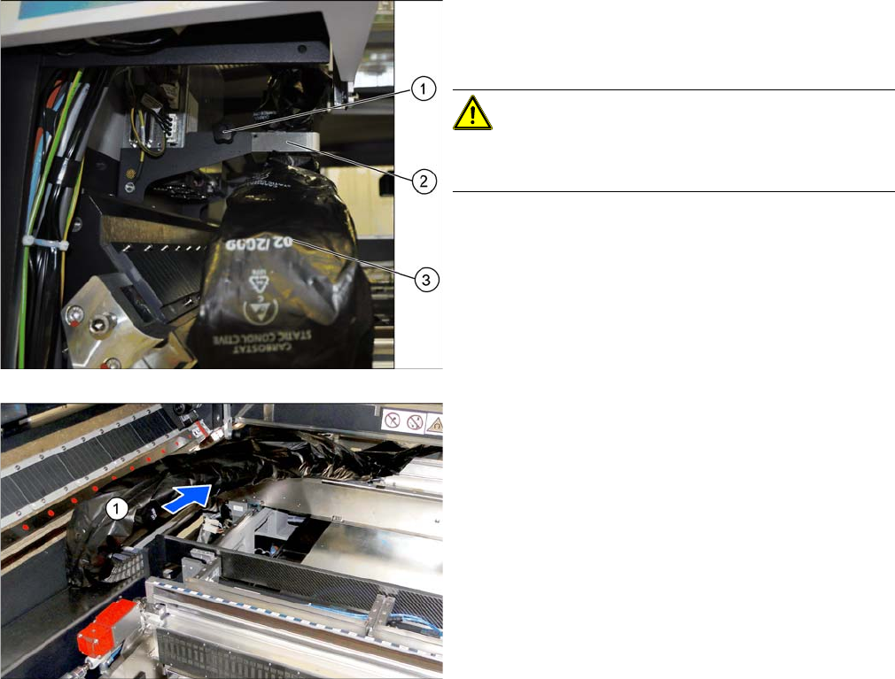
► Loose the fixture screw (1) on the holder (2).
► Carefully disconnect the trailing cable (3) from its
holder.
CAUTION!
Take care when handling the trailing cable!
Take care not to damage the foil or the trailing cable.
► Place the holder and the fixture screw in the "Pre
-
pared case" for fitting back into place later on.
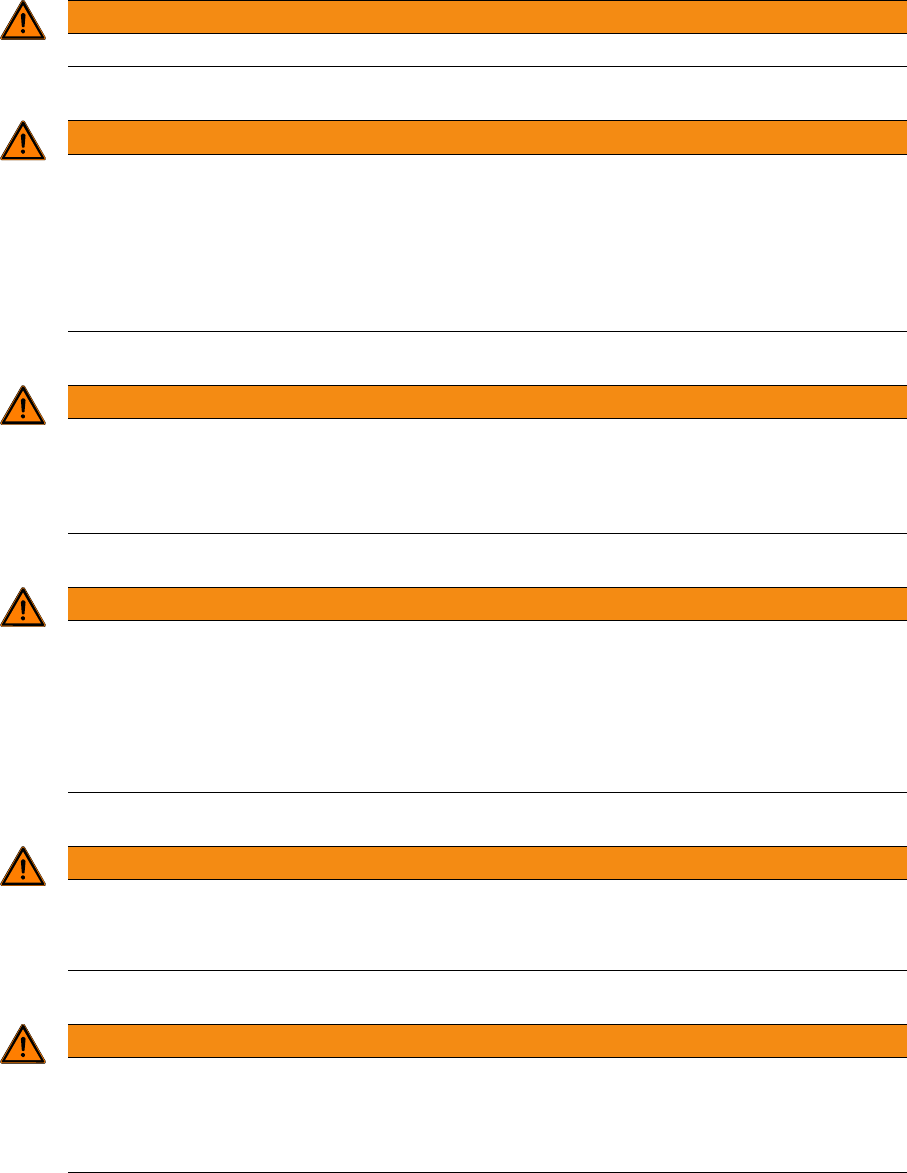
► Take the trailing cable (1) and place it carefully to
-
wards the front, into the machine.
assembly
Gantry Preparations 3.2.1 The Gantry Lift
102 Reconfiguration Kit Twin VHF with Gantry Reconfiguration Kit Twin VHF mit Por
-
3.2
3.2 Gantry Preparations
Gantry Preparations
The gantry is packed in a transportation crate. You need the gantry lift to transport the gantry.
3.2.1
3.2.1 The Gantry Lift
The Gantry Lift
The gantry lift is needed for transportation and assembly purposes. Also observe the following instruc
-
tions:
WARNING
The gantry may only be transported with the help of the gantry lift.
WARNING
Observe the manufacturer's operating guide!
Please consult the operating guide supplied for details of how to handle the gantry lift and for
all safety-relevant aspects. Observe the instructions therein.
► Observe the safety instructions in the manufacturer's operating guide.
► Observe all safety instructions in this assembly guide when transporting and assembling
the gantry.
WARNING
Verification
► The operator is obligated to check the lifting assistance for visible damage at least once at
shift start or in case of an abnormality, anomaly, event and to give notice of such damage
immediately.
WARNING
Brake, wheels
► Lock the wheels by pushing the brake rod down/forward as far as possible before loading
or unloading the lifting assistance.
► Lock the foot brake after every moving procedure and/or after arriving the required position
in order to prevent inadvertent rolling of the lifting assistance. Release the brake before
moving it again.
WARNING
Fixtures
► Never loosen the fastening of loads, if these are still in use. Always ensure a safe standing
of the load before release it.
WARNING
Risk of injury
► When using mobile (tiltable, swiveling, inclinable) load pickup devices always make sure
that no own or different parts of the body and also no other obstacles are to be located in
the entire movement range of load and load pickup devices.