00197454-01_AI_Portal_40mm_TwinVHF_SX12_de_en.pdf - 第119页
assembly 3.7.1 Empty Tape Duct Intermediate Plate Final Work Reconfiguration Kit Twin VHF with Gantry Re configuration Kit Twin VHF mit Portal 119 3.7 3 . 7 F in a l W o r k Final Work 3.7.1 3 . 7 . 1 E m p t y T a p e D…
assembly
Trailing Cable Connection 3.5.1 Replacing/Fitting the End Position Buffers
118 Reconfiguration Kit Twin VHF with Gantry Reconfiguration Kit Twin VHF mit Por
-
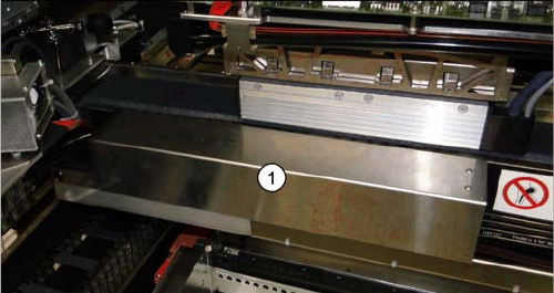
► Fit the cover (1) over the gantry interface.
assembly
3.7.1 Empty Tape Duct Intermediate Plate Final Work
Reconfiguration Kit Twin VHF with Gantry Reconfiguration Kit Twin VHF mit Portal 119
3.7
3.7 Final Work
Final Work
3.7.1
3.7.1 Empty Tape Duct Intermediate Plate
Empty Tape Duct Intermediate Plate
If tapes with high components are processed, you will need to remove the empty tape duct intermediate
plate when upgrading a gantry with TwinHead or CPP head and stationary camera.
If you are only using component with tapes up to 12 mm, keep the intermediate plate in the empty tape
duct.
3.7.2
3.7.2 Stowing the Gantry Carrier and the Prepared Case
Stowing the Gantry Carrier and the Prepared Case
Stowing the gantry carrier in the transportation crate
► Use the gantry lift to move the gantry carrier into the transportation crate.
► Fix the gantry carrier into place in the transportation crate, with the 4 fastening screws.
► Release the gantry carrier from the gantry lift and move the gantry lift to one side.
► Place the foam cover for the placement head in the transportation crate.
► Close the front and top cover on the transportation crate.
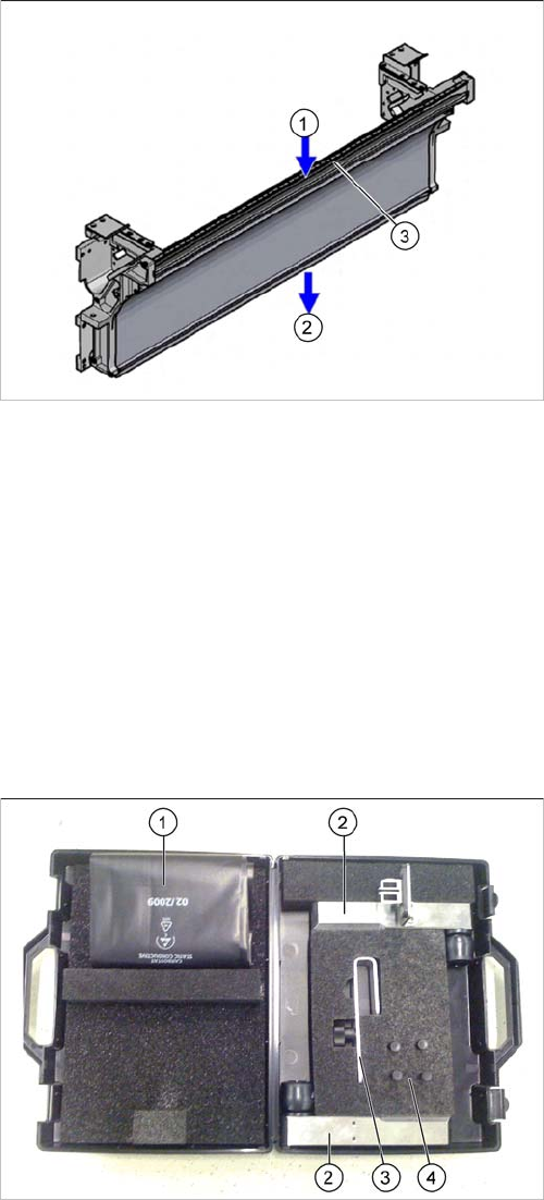
Placing assembly parts in the "Prepared" case
1. Inlet slot for empty tapes
2. Outlet slot for the empty tapes above the pneumatic
tape cutter
3. Dividing plate for tapes < 12 mm (can be removed for
tapes > 12 mm)
You have removed the following parts which you will
need to dismantle the gantry later on. Keep these parts in
the "Prepared" case.
▪ The long end position buffer
▪ A green lever as transportation lock for the gantry
▪ Two transportation locks for the placement head
▪ Black plastic foil for trailing cable
▪ Trailing cable holder with knurled head screw
assembly
Final Work 3.7.3 Checking the Gantry Coding
120 Reconfiguration Kit Twin VHF with Gantry Reconfiguration Kit Twin VHF mit Por
-
3.7.3
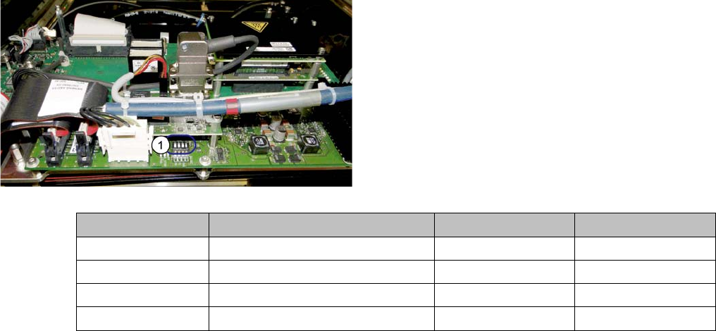
3.7.3 Checking the Gantry Coding
Checking the Gantry Coding
► Check the DIP switch (1) for the gantry coding of the
locations on the head interface.
Switch Designation Gantry 1 Gantry 2
1 DC/DC OFF OFF
2FANOFFOFF
3P1OFFON
4P0OFFOFF