YSH20_Ope_E.pdf - 第100页
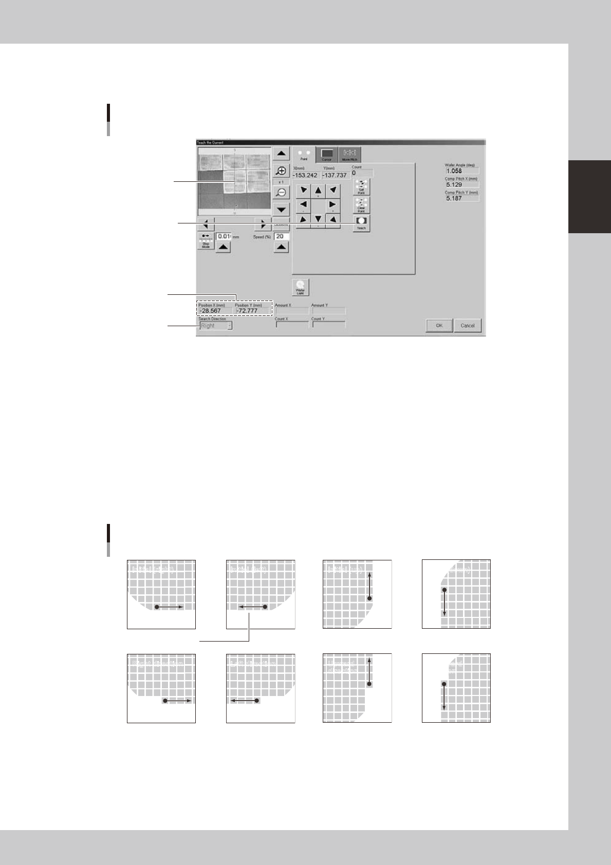
2-43 2 asic operation 4. Position teach (current) 1 Pr ess the [PosT ch] button. Align the center of component with the center of cross hairs. Press this button to determine the position. Current position T each screen…
2-42
2
asic operation
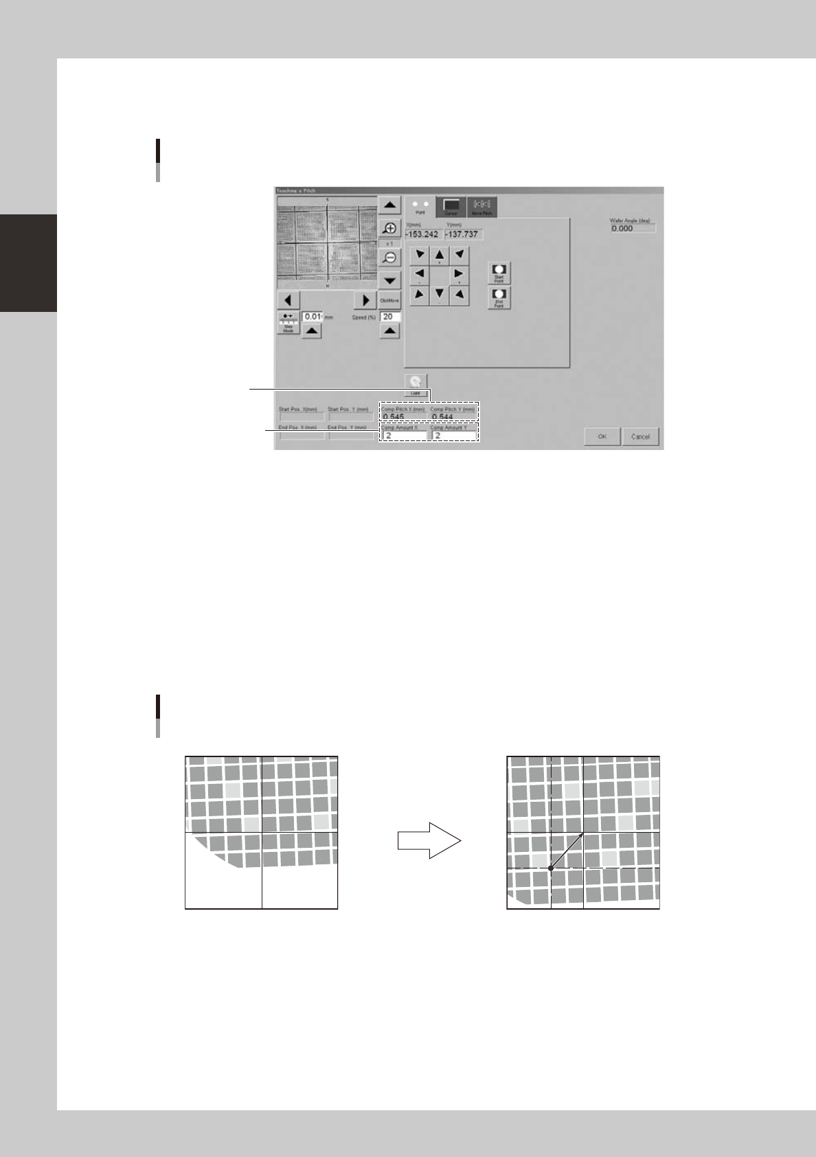
3. Pitch teach
1
Press the [PitchTch] button.
Enter the number of
components in X and
Y directions.
Calculated pitch
Teach screen
Pitch teach
24236-H0-00
2
Determine the start point (reference point).
Align with a position used as the reference point by "Point" or "Cursor" teach, and press the [Start Point]
button.
3
Enter the number of components in XY directions.
The number of components entered here is used for pitch calculation.
4
Determine the end point.
Move the camera to another reference position that is shifted by the number of components in XY
directions entered in step 3, and press the [End Point] button.
The component pitch is automatically calculated based on the start and end point coordinates and the
number of components.
Pitch teaching
Start point (center of cross hairs)
End point (center of cross hairs)
Use arrow keys to move camera
by number of components in XY
directions.
23237-H0-00
5
Check the pitch that was changed.
1. Select the [Move Pitch] tab.
2. Press an arrow button to check that the camera moves a distance equal to the component pitch in
the direction of the arrow.
6
Register the pitch.
Press the [OK] button. The "Teach the Pitch" screen closes and the calculated pitch is registered in the
"Comp Pitch X" and "Comp Pitch Y" parameters.
2-43
2
asic operation
4. Position teach (current)
1
Press the [PosTch] button.
Align the center of
component with the
center of cross hairs.
Press this button to
determine the position.
Current position
Teach screen
Position teach
Search direction
24237-H0-00
2
Move to the first component.
Use the arrow keys to move to the first component.
3
Teach the center of the component.
Using multi-point teaching, teach the center of the first component on the basis of the orientation flat.
4
Check the teaching result.
When a new component was used, the XY position (current position) is usually set to 0.00 (center of
dicing frame). After the current position is correctly taught, the corresponding coordinates are
displayed in the XY positions.
5
Check the search direction.
Change the search direction as needed.
Search direction
Initial (right) Initial (left) Initial (up) Initial (down)
Right direction Left direction Upward
direction
Downward
direction
Orientation flat
23238-H0-00
6
Register the position.
Press the [OK] button. The "Current Teach" screen closes and the current position is registered in the
"Current Pos. X" and "Current Pos. Y" parameters.
2-44
2
asic operation
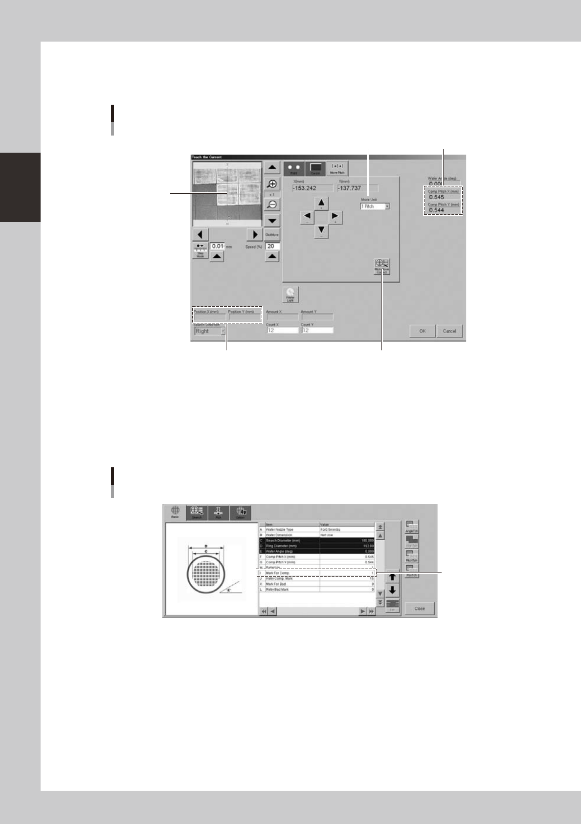
n
Pitch movement
The camera can be moved at a specified pitch each time an arrow key on the [Move Pitch] tab is pressed. The center of
component can be tracked by using pitch movement correction.
This button should be pressed.
Current position
Teach screen
Pitch movement
Currently set pitch
Move Unit (pitch to move)
Center of cross
hairs moves to
center of component
each time a pitch
movement is
performed.
24240-H0-00
"Move Unit" (pitch to move)
The default is "1 Pitch" but "2 Pitch" and "5 Pitch" can also be selected.
[Pitch Move Correct] button
When this button is pressed, the component position is recognized during pitch movement and is displayed in the center
of the screen. To enable pitch movement correction, a mark number must be set in the "I: Mark For Comp." parameter on
the [Basic] tab of the "Wafer Information" screen.
Set this parameter.
Wafer information
"Mark For Comp." parameter
24241-H0-00