YSH20_Ope_E.pdf - 第37页
1-1 1 Part names and functions 1. Machine main unit A standard machine has the following configurations after installation is complete. Names and functions of major parts of the main unit are illustrated below . Part nam…

Chapter 1 Part names and functions
Contents
1
4
7
3.1 Keyboard and mouse 1-7
8
4. Head assembly 1-9
4.1 Component pick-and-place head 1-10
4.1.1 F head 1-10
4.1.2 4M head 1-10
4.1.3 Component recognition cameras 1-11
4.2 Nozzle types 1-12
4.2.1 Nozzles for F head 1-12
3
5. Component supply section 1-14
5.1 Supplying components from feeder plates 1-14
5.2 Supplying components from a wafer tray changer 1-15
6.
Conveyor unit 1-17
6.1
Conveyor unit 1-17
6.2 Conveyor sensor positions 1-18
7. Axis configuration 1-19
1-1
1
Part names and functions
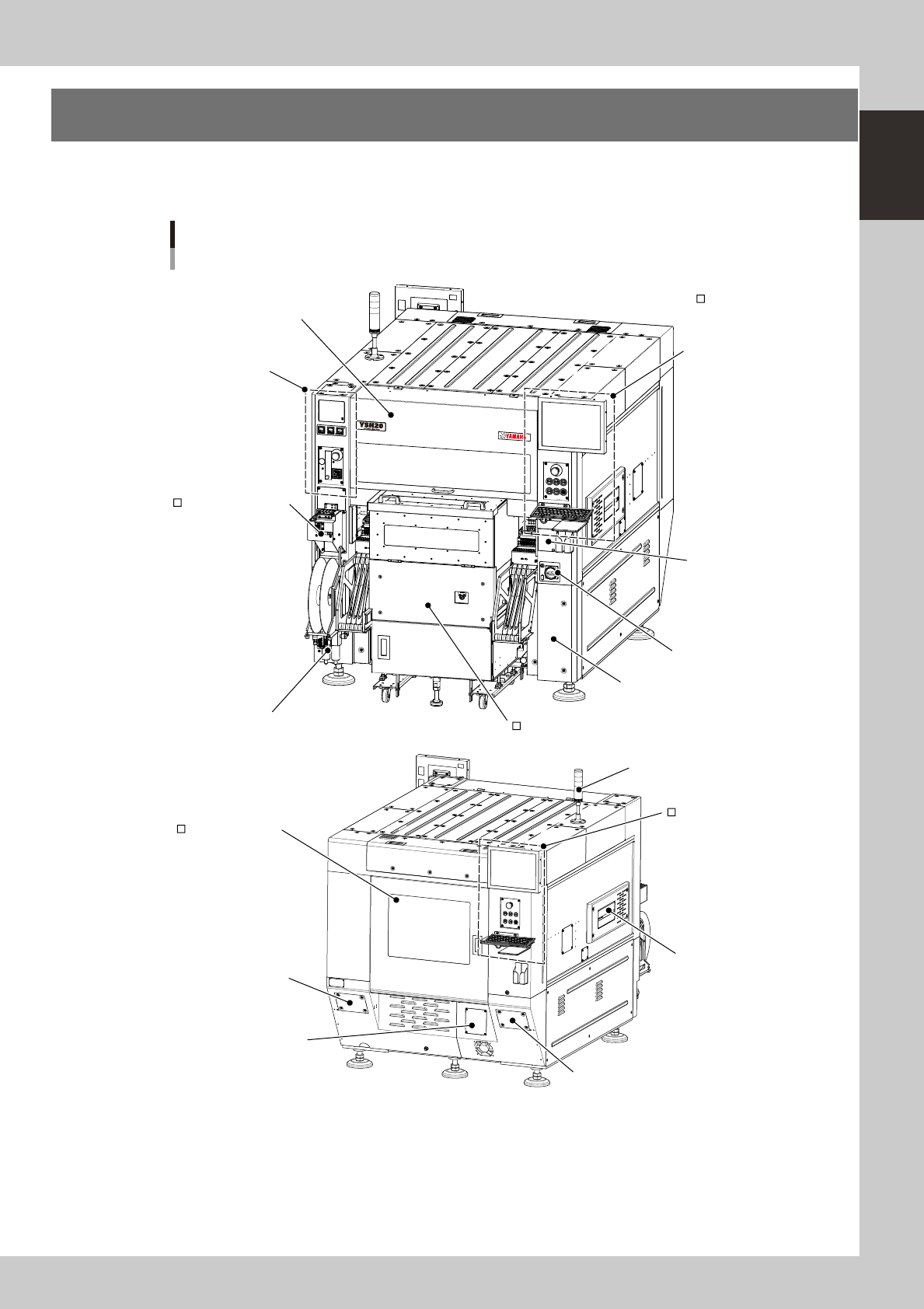
1. Machine main unit
A standard machine has the following configurations after installation is complete. Names and functions of
major parts of the main unit are illustrated below.
Part names
N Signal light (with buzzer)
N Safety cover
N Air/temperature
adjustment unit
SS feeder temporary
setup station
N Compressed air connector / air filter
N Main switch
N Power connection terminals
N Muzzle plate
Wafer supply unit (wafer tray changer)
N USB port
N
Operation panel and
data input unit
N : Standard units
: Options
Operation panel and
data input unit
Safety cover (rear)
N Filer for vacuum pump
N Machine-to-machine
interface connector
N Machine-to-machine interface connector
23100-H0-00
1-2
1
Part names and functions
n
Signal light (with buzzer)
Indicates current operating conditions of the machine with a green, yellow and red light, or green, white and blue light
explained below. The buzzer at the bottom of the signal light sounds if an error or abnormal condition occurs. (The
volume can be adjusted by turning the ring right or left.)
Machine status Example Green
Red/
White
Yellow/
Blue
Warm-up or automatic operation ON ----- -----
Emergency stop ----- ON -----
System error
(with buzzer ON)
• Excessive current
• Secondary limit is exceeded
----- ON -----
Operation or board data error
(with buzzer ON)
• Pickup error, recognition error
• Data check error, etc.
----- ----- ON
Components cannot be used.
• Components run out.
• Tray changer door is open.
----- ----- Flashing
n
Safety cover
This cover must be closed during operation. If opened, emergency stop is triggered.
n
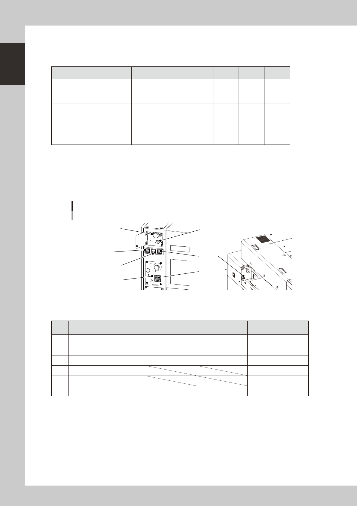
Air adjustment valve, air supply/shutoff switch
Use the air valve when adjusting the supply air pressure to the specified level. To shut off the air supply and discharge
the remaining air.
Air pressure / temperature adjustment unit
1
2
3
4
5
Air adjustment valve
Rear side
Air supply/shutoff switch
6
23101-H0-00
n
Pressure gauge / temperature adjustment unit
Adjust the air pressures and temperature so that they show the following values.
Description Setting
Pressure-drop
detection level
Note
1 Setting air pressure 0.40MPa to 0.41MPa 0.33MPa
2 Internal vacuum pump pressure -76.5kPa or more -53.3kPa
3 External vacuum pump pressure -90kPa or more -80kPa Should by prepared by user.
4 Wafer heater temperature
5 Wafer heater's air flow meter
6 Setting air pressure
(For load control)
0.40MPa to 0.41MPa 0.33MPa
n
Safety cover (rear)
When replacing a push-up pin in the wafer tray changer or servicing it, open this safety cover.
n
Muzzle plate
Use this plate to ensure safety for the entrance and exit openings of the board conveyor.