YSH20_Ope_E.pdf - 第83页
2-26 2 asic operation 3 Set the tape in the tape feeder . Insert in the hole on the rear of the feeder . Setting the tape T ape 23207-H0-00 c …
2-25
2
asic operation
4. Preparing the component supply unit
4.1 Tape feeders
4.1.1 Setting the tape
c
Always use a tape set station or a power station to set the tape. The tape cannot be set directly on the machine.
1
Set the feeder.
Place the feeder in the temporary tape set station or power station for the off-line setup.
Setting the feeder
Handle
Feeder
Tape set station
23205-H0-00
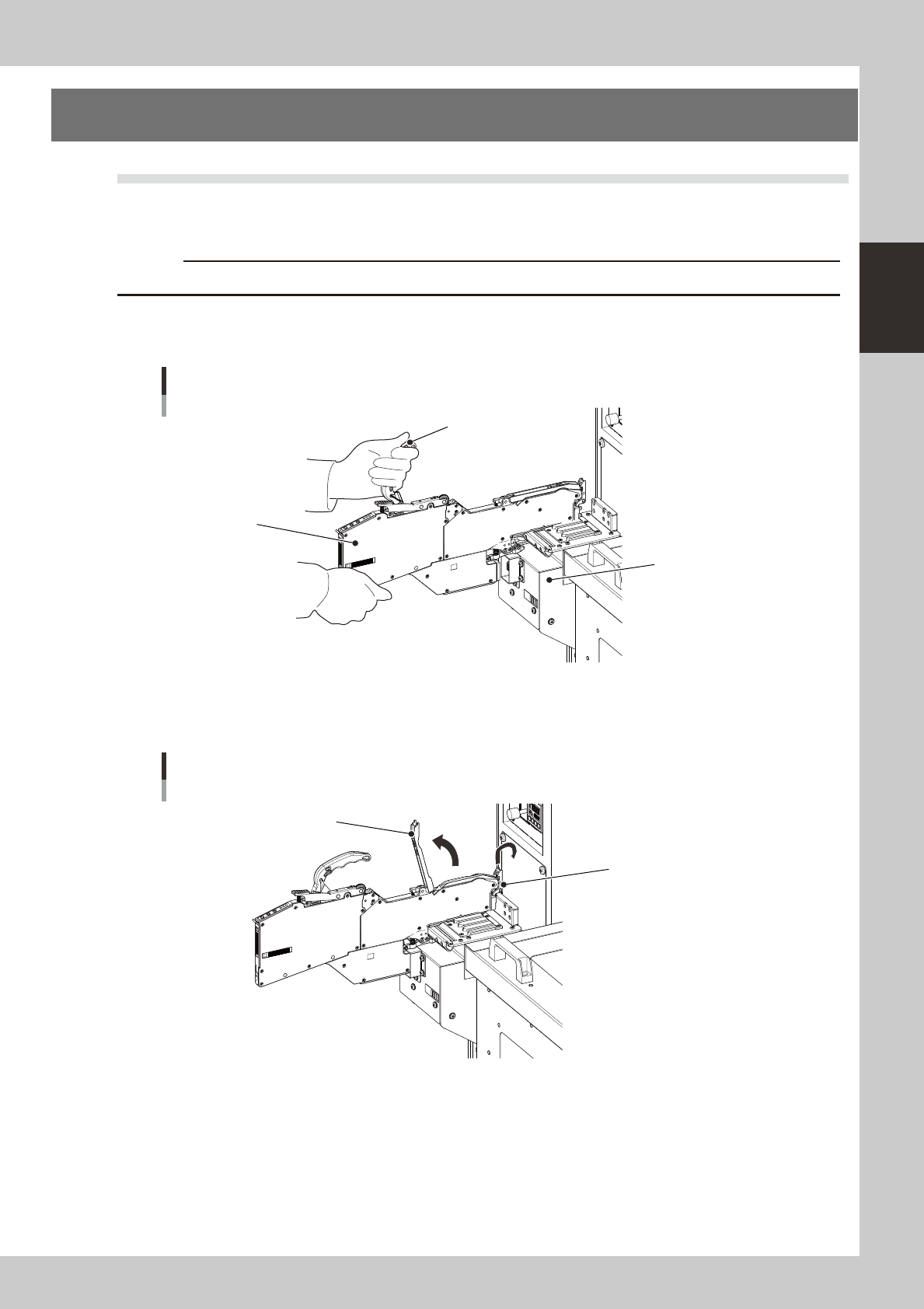
2
Raise the tape guide assembly.
Lower the front lever for the tape guide while lifting it, and raise the tape guide assembly.
Raising the tape guide assembly
Tape guide assembly
Tape guide front lever
23206-H0-00
2-26
2
asic operation
3
Set the tape in the tape feeder.
Insert in the hole on the rear of the feeder.
Setting the tape
Tape
23207-H0-00
c
4
Peel off the top tape.
The tape consists of 2 layers. One is a "carrier tape" holding the electronic component and the other is a
"top tape" covering the upper surface of the component. Peel off the top tape.
5
Set the carrier tape.
Run the carrier tape through the hole in the tape guide front lever.
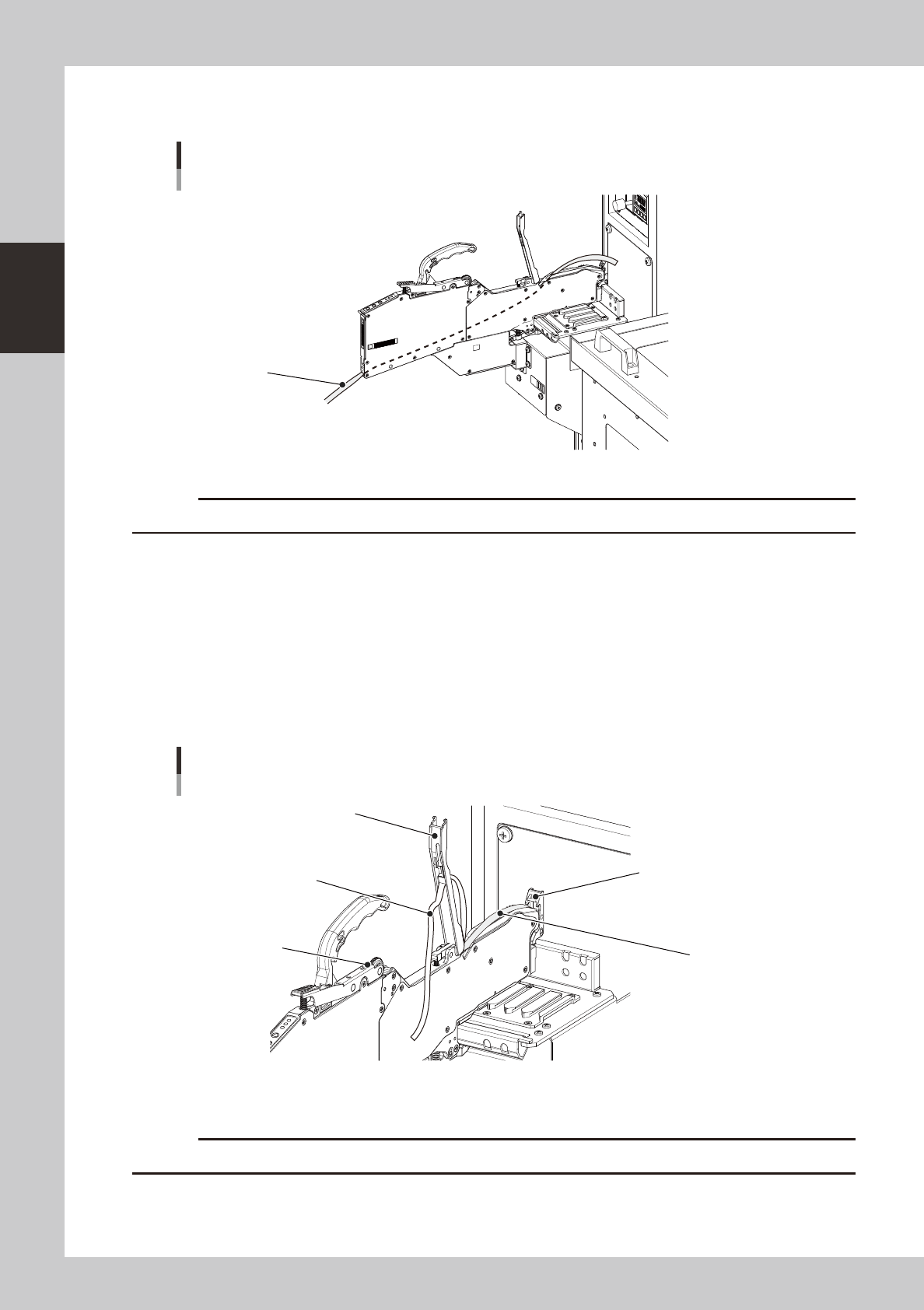
6
Set the top tape.
Run the top tape through the notch in the tape guide assembly. Be sure to pull out enough tape so the
top tape reaches the take-up roller.
Carrier tape and top tape
Tape guide assembly
Take-up roller
Top tape
Carrier tape
Tape guide front lever
23208-H0-00
c
2-27
2
asic operation
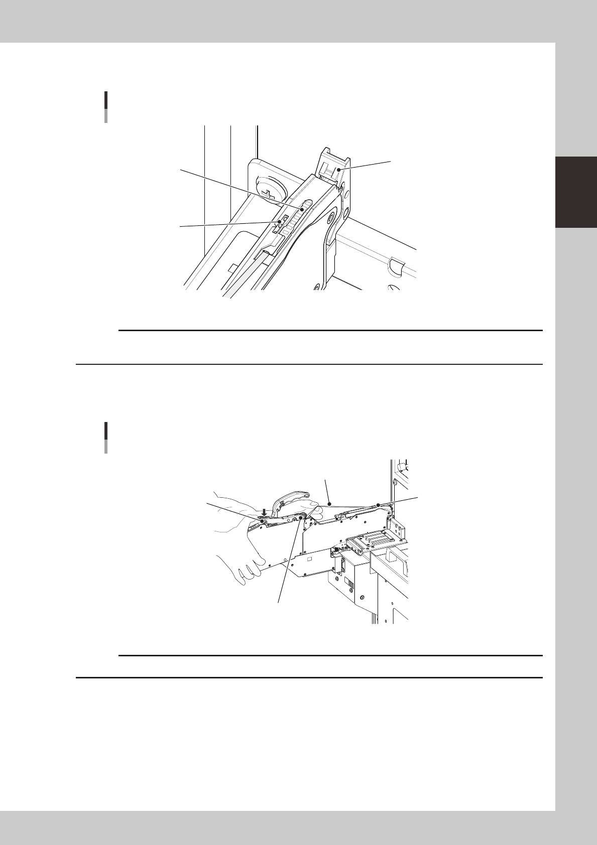
7
Clamp the tape guide assembly.
Set the carrier tape so it engages with the teeth on the sprocket.
Clamping the tape guide assembly
Sprocket teeth
Tape guide front lever
Carrier tape
23209-H0-00
c
guide assembly during clamping.
8
Set the top tape in the take-up roller.
Clamp the section of the take-up roller lever shown in the photo to form a gap in the take-up roller,
insert some of the top tape into that gap, then release the take-up roller lever to grip the top tape.
Setting the top tape
Top tape
Take-up roller
Take-up roller lever
Tape guide assembly
23210-H0-00
c
Check that the top tape has not become twisted between the take-up roller and the tape guide assembly.