YSH20_Ope_E.pdf - 第39页
1-3 1 Part names and functions n Connectors for dipping station Connectors for the dipping station power supply and signal connection. One connector each is installed on the left and right sides. n Feeder setup section S…
1-2
1
Part names and functions
n
Signal light (with buzzer)
Indicates current operating conditions of the machine with a green, yellow and red light, or green, white and blue light
explained below. The buzzer at the bottom of the signal light sounds if an error or abnormal condition occurs. (The
volume can be adjusted by turning the ring right or left.)
Machine status Example Green
Red/
White
Yellow/
Blue
Warm-up or automatic operation ON ----- -----
Emergency stop ----- ON -----
System error
(with buzzer ON)
• Excessive current
• Secondary limit is exceeded
----- ON -----
Operation or board data error
(with buzzer ON)
• Pickup error, recognition error
• Data check error, etc.
----- ----- ON
Components cannot be used.
• Components run out.
• Tray changer door is open.
----- ----- Flashing
n
Safety cover
This cover must be closed during operation. If opened, emergency stop is triggered.
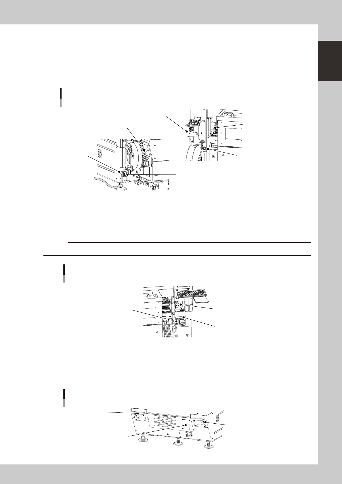
n
Air adjustment valve, air supply/shutoff switch
Use the air valve when adjusting the supply air pressure to the specified level. To shut off the air supply and discharge
the remaining air.
Air pressure / temperature adjustment unit
1
2
3
4
5
Air adjustment valve
Rear side
Air supply/shutoff switch
6
23101-H0-00
n
Pressure gauge / temperature adjustment unit
Adjust the air pressures and temperature so that they show the following values.
Description Setting
Pressure-drop
detection level
Note
1 Setting air pressure 0.40MPa to 0.41MPa 0.33MPa
2 Internal vacuum pump pressure -76.5kPa or more -53.3kPa
3 External vacuum pump pressure -90kPa or more -80kPa Should by prepared by user.
4 Wafer heater temperature
5 Wafer heater's air flow meter
6 Setting air pressure
(For load control)
0.40MPa to 0.41MPa 0.33MPa
n
Safety cover (rear)
When replacing a push-up pin in the wafer tray changer or servicing it, open this safety cover.
n
Muzzle plate
Use this plate to ensure safety for the entrance and exit openings of the board conveyor.
1-3
1
Part names and functions
n
Connectors for dipping station
Connectors for the dipping station power supply and signal connection. One connector each is installed on the left and
right sides.
n
Feeder setup section
Set SS feeders (tape components) or a dipping station here.
n
Temporary tape set station (option)
This is used for setting tape components in SS feeders and for changing the feed pitch.
Supply air connector / feeder-related parts
SS feeder temporary setup station
Reel holder
Feeder setup section
Supply air
connector
Air/mist filter
Dipping station connector
23102-H0-00
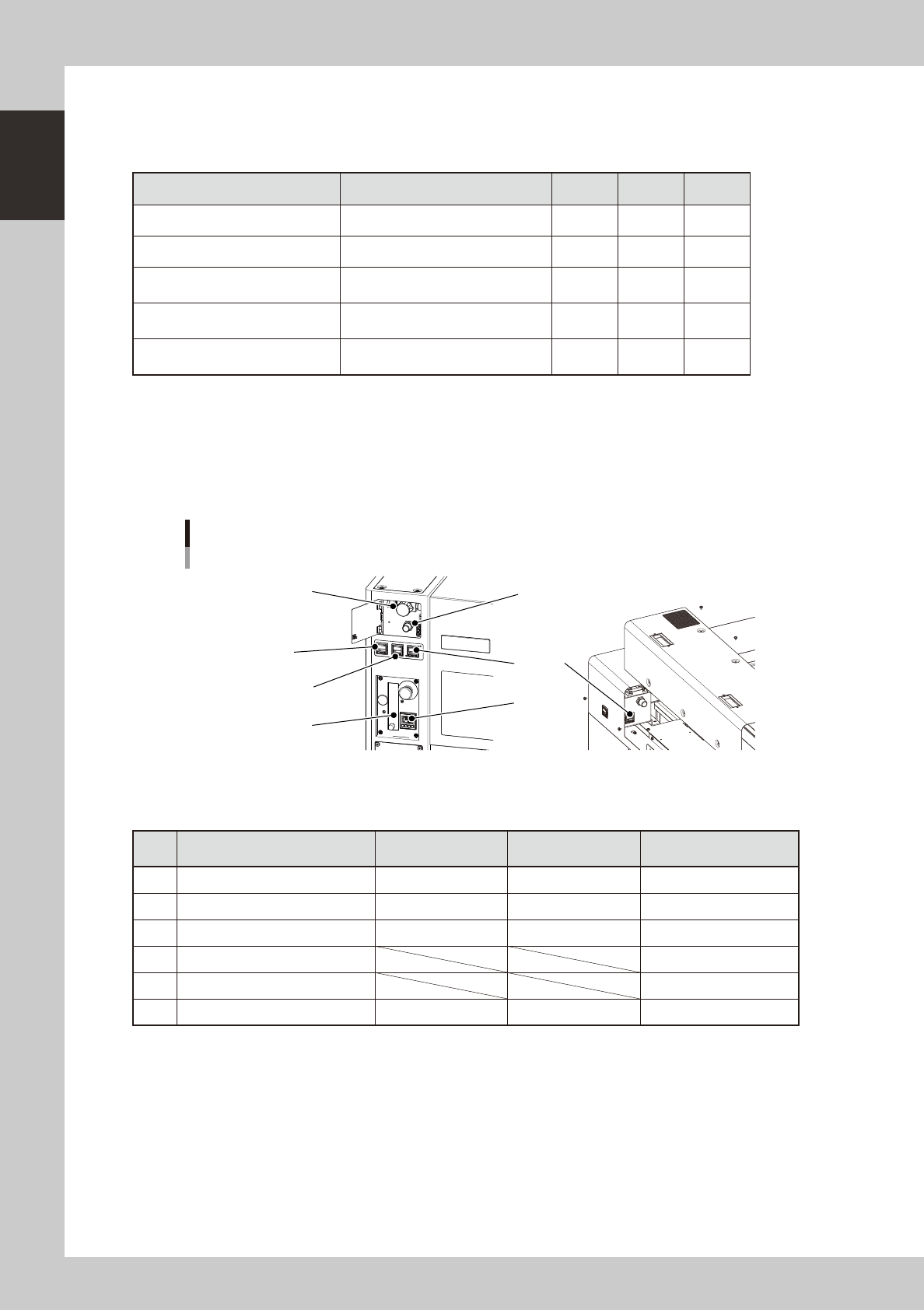
n
USB port
Use this USB port when making a data backup or upgrading the software version.
n
Power switch
Turns on or off the power to the machine. The power is on when turned to the right.
c
Wait about 2 seconds before turning the power switch back on after turning it off.
Main switch
USB port
Main switch
Connector for dipping station
23103-H0-00
n
Machine-to-machine interface connectors (input/output signals between machines)
The machine ejects the board when it receives a signal from the machine in the next process, and then sends a signal to
the machine in the preceding process to request another board. The interface connector labeled "NEXT INTERFACE"
connects to the machine in the next process, and the interface connector labeled "PREVIOUS INTERFACE" connects to
the machine in the preceding process.
Machine-to-machine interface connectors
N Filter for vacuum pump
(behind cover)
N Machine-to-machine
interface connector (behind cover)
N Machine-to-machine
interface connector (behind cover)
23104-H0-00
1-4
1
Part names and functions
2. Optional units
This section describes the part names and functions of optional units.
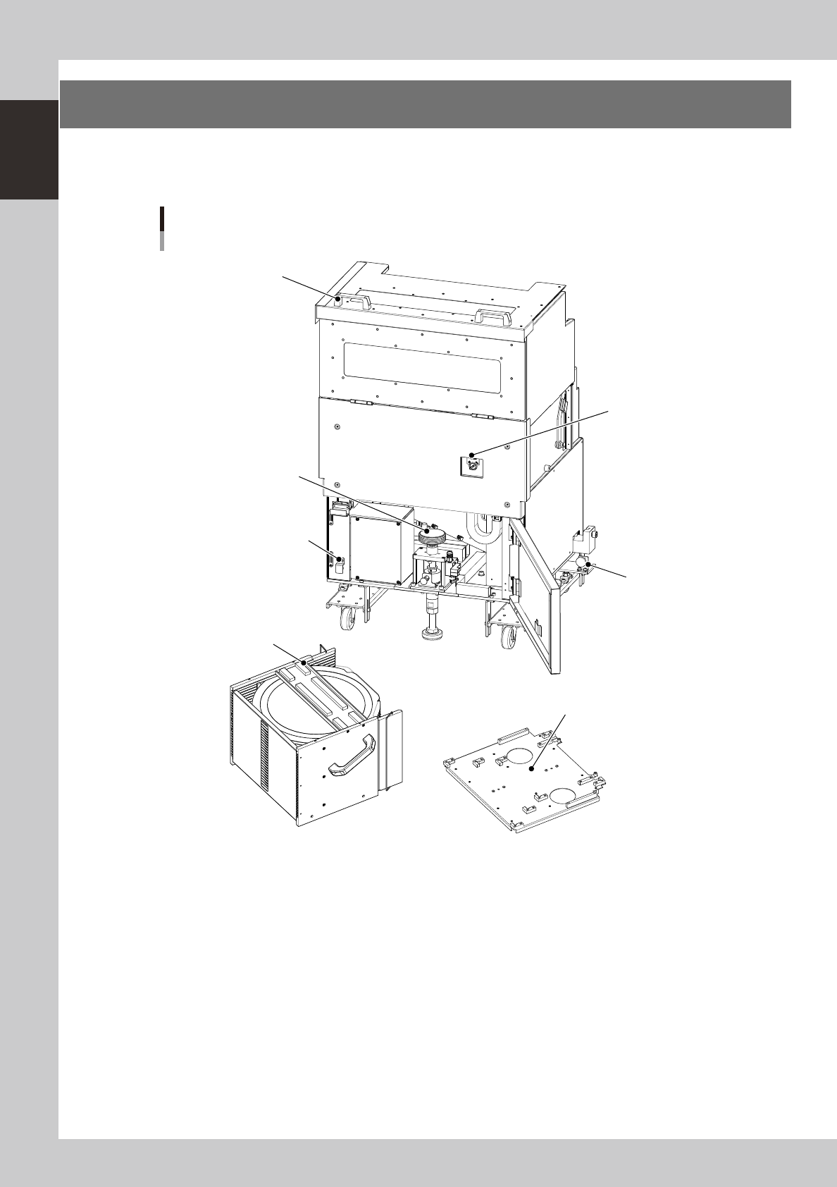
n
Magazine setup unit
Wafer tray changer
Magazine side
Magazine position
selector switch
Jack lift handle
LZ-axis brake release button
Lock knob
Cover open/close handle
Magazine
Magazine size attachment (6-inch / 8-inch wafer pallet)
23105-H0-00
Lock knob (one each on right and left)
Use these knobs to attach or detach the magazine setup unit.
Jack lift handle
Use this handle to lift the wafer storage unit to a position where wafers can be taken out.
Cover open/close handle
When exchanging the magazine, pull this handle toward you to open the cover.
LZ-axis brake release button
Do not use this button in normal operation. Use it only when the LZ-axis brake must be released.
Magazine position selector switch
Setting this switch in the "SET UP" position moves the elevator unit to the magazine exchange position (top position).
Leave this switch in the "AUTO" position except for exchanging the magazine.