YSH20_Ope_E.pdf - 第73页
2-16 2 asic operation n Manual feeder operation [Unit] - [Feeder] screen 1 4 7 2 6 5 3 24210-H0-00 Button name Function 1 Feed Each time pressing this button advances the tape at the specified pitch. 2 Back Each time p…
2-15
2
asic operation
n
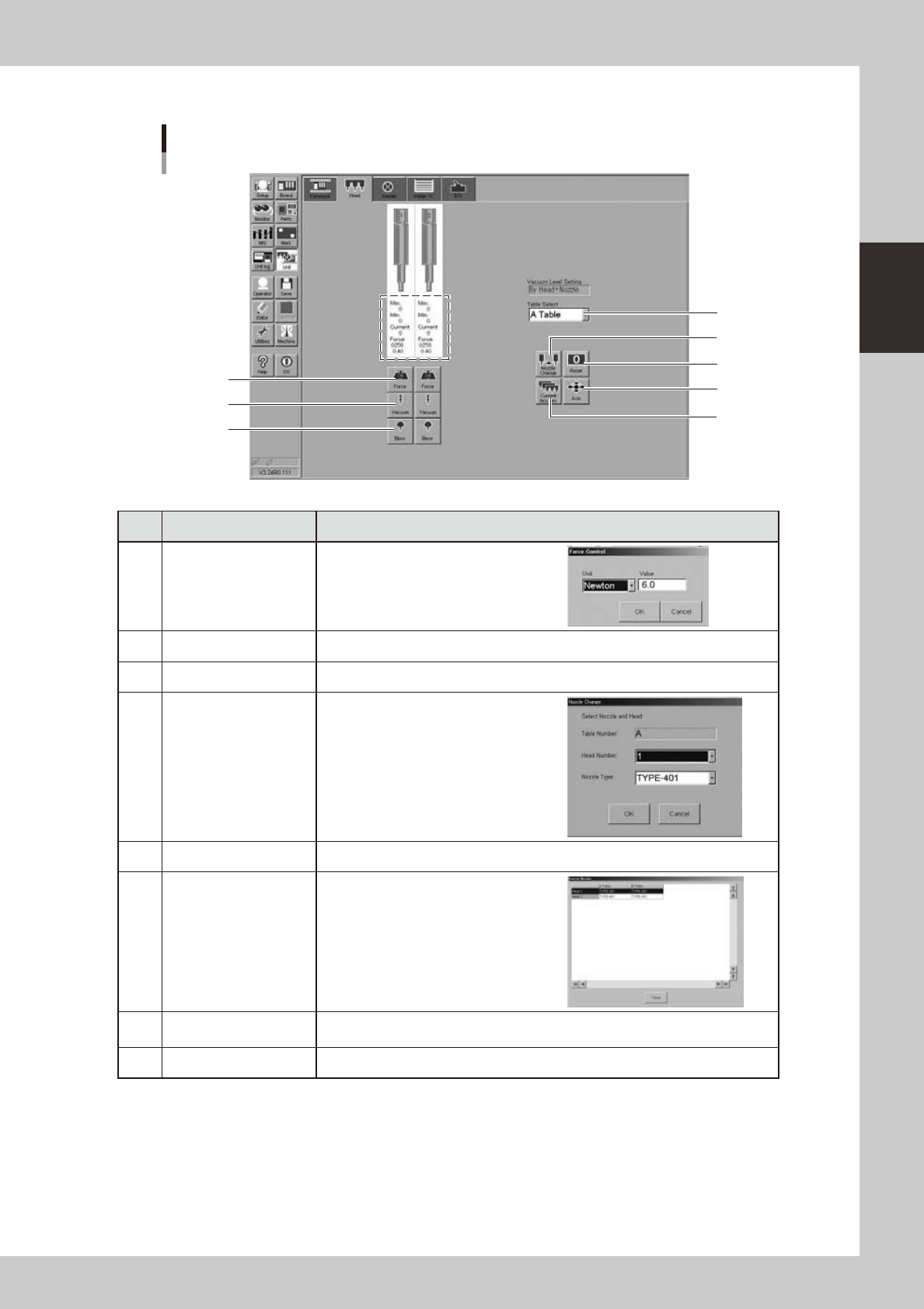
Manual head operation
[Unit] - [Head] screen
Example of FF head
2
1
3
5
4
8
7
6
24207-H0-00
Button name Function
1 Force
Use this button to set a load manually
or check the set load. Units are either in
Newtons or bits.
2 Vacuum Turns the vacuum of each head on or off.
3 Blow Turns the air blow in each head on or off.
4 Nozzle Change
When the machine is equipped with a
nozzle station, pressing this button opens
the "Nozzle Change" dialog box. Specify
the head and nozzle type to perform
nozzle change.
5 Reset Resets the values enclosed by a dotted line on the above screen.
6 Current Nozzles
Shows a list of nozzle types currently
attached to each head.
7 Axis
Opens the "Move Axis" screen. This is the same as the [Axis] button on the [Unit]-
[Conveyor] screen.
8 Table Select Select the table for operation.
2-16
2
asic operation
n
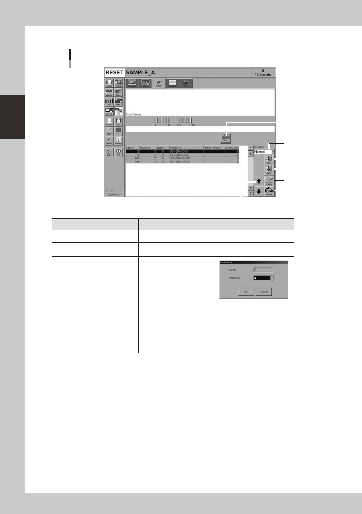
Manual feeder operation
[Unit] - [Feeder] screen
1
4
7
2
6
5
3
24210-H0-00
Button name Function
1 Feed Each time pressing this button advances the tape at the specified pitch.
2 Back
Each time pressing this button moves the tape backward at the specified
pitch.
3 Feeder Setting
Pressing this button opens the
feeder setting dialog box that
allows selecting a feed pitch from
2 to 56mm.
Set the feed pitch and press the
[OK] button. The set feeder pitch
is stored in memory.
4 Speed
Select the feed speed from the drop-down list. The selectable speeds
are "Normal", 90, 80, … 10%.
5 Reload Clears the feeder condition (memory) and reloads the setting.
6 Up/down arrow Moves the selected row up or down.
7 Plate Information Allows you to check the version of the plate board in the feeder plate.
2-17
2
asic operation
n
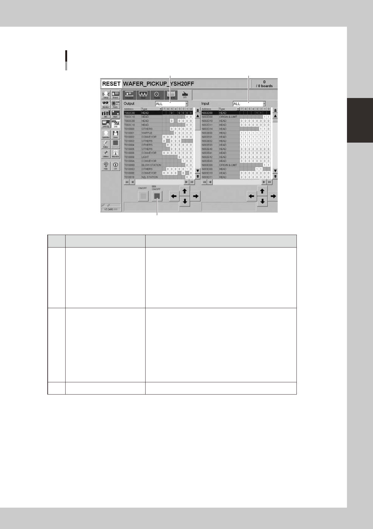
Manual I/O operation
[Unit] - [I/O] screen
1 2
3
24212-H0-00
Button name Function
1 Select output display group
Select the output group for display in the "Output" status list. The
following groups can be selected:
• ALL
• NSTA (nozzle station)
• DUMP STATION
• CONV (conveyor)
• HEAD
• BSTA (blow station)
• OTHERS
2 Select input display group
Select the input group for display in the "Input" status list. The
following groups can be selected:
• INTLCK (interlock)
• SRV (servo origin limit)
• FDR (feeder)
• NSTA (nozzle station)
• CONV (conveyor)
• SPARE
• DUMP STATION
• BSTA (blow station)
• OTHERS
3 ON/OFF Turns the selected valve on or off.