YSH20_Ope_E.pdf - 第98页
2-41 2 asic operation 2. Alignment teach n NOTE T o per for m alignment teaching, wafer fiducial marks must be set in mark information. Also, the "E. Align Mark" parameter displayed on the [Option] tab of the …
2-40
2
asic operation
1. Angle teach
1
Set a wafer component.
1. On the Setup screen, press the [TrayCnt] button in the "Utility" group box.
2. Select the component whose position you want to teach.
3. Press the [Angle Tch] button.
The component is extracted from the magazine and set on the stage. The following screen then
appears.
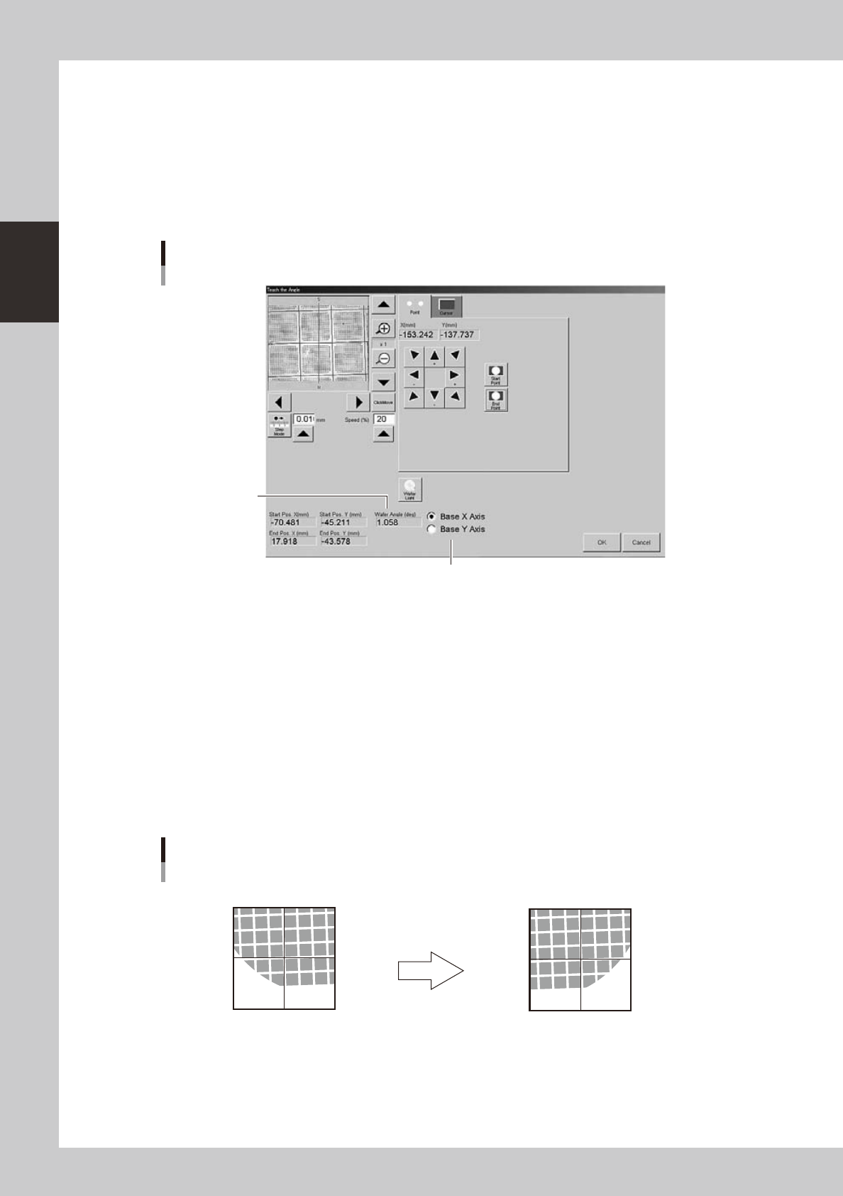
Select X or Y as reference axis.
Calculated angle
Teach screen
Angle teach
24235-H0-00
2
Select the X or Y axis as the reference axis.
Normally, select the default "Base X axis".
3
Determine the start point.
Align with a position used as the reference point (start point) by "Point" or "Cursor" teach, and press the
[Start Point] button.
Specify a corner of the component because other positions near the center of the component may not
be calculated accurately. If it is difficult to see the component, press the [Wafer Light] button and
adjust the brightness.
4
Determine the end point.
Move the camera in the X direction to align with the end point by "Point" or "Cursor" teach, and press
the [End Point] button.
Angle teach start point and end point
Start point (center of cross hairs)
Use arrow keys to move camera.
End point (center of cross hairs)
23236-H0-00
5
Check the result.
The teaching result is displayed in the "Wafer Angle" box.
2-41
2
asic operation
2. Alignment teach
n
NOTE
To perform alignment teaching, wafer fiducial marks must be set in mark information. Also, the "E. Align Mark"
parameter displayed on the [Option] tab of the "Wafer Information" screen must be set to other than "Not Use". (The
"Wafer Information" screen opens when you press the [Wafer] button on the [Parts]-[Tray] tab.)
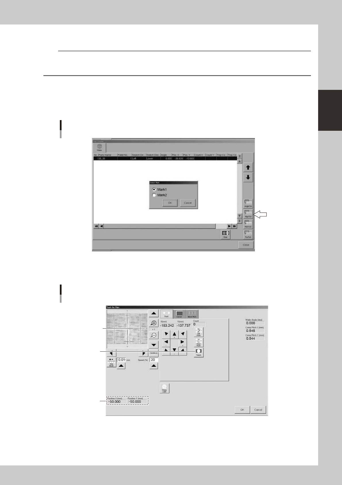
1
Press the [AlignTch] button
2
Select the mark.
Select the mark from the "Select Mark" dialog box. The wafer camera then moves to the selected mark
position.
Selecting the mark for alignment teach
24238-H0-00
3
Teach the mark position.
Teach the mark position or the center of component used as the mark.
Press this button to
determine the position.
Teach screen
Alignment teach
Center coordinates
of mark
Align the mark or the
center of component
used as the mark
with the center of
cross hairs.
24239-H0-00
2-42
2
asic operation
3. Pitch teach
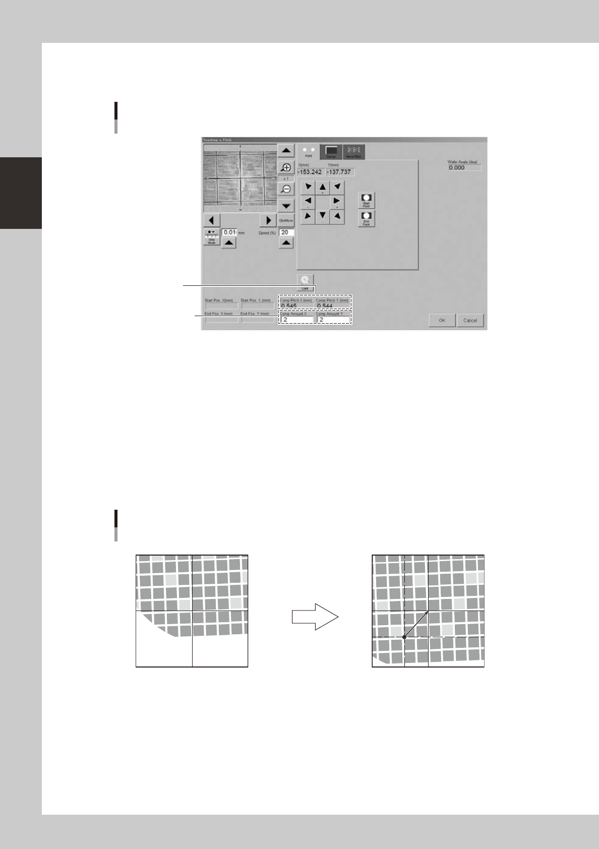
1
Press the [PitchTch] button.
Enter the number of
components in X and
Y directions.
Calculated pitch
Teach screen
Pitch teach
24236-H0-00
2
Determine the start point (reference point).
Align with a position used as the reference point by "Point" or "Cursor" teach, and press the [Start Point]
button.
3
Enter the number of components in XY directions.
The number of components entered here is used for pitch calculation.
4
Determine the end point.
Move the camera to another reference position that is shifted by the number of components in XY
directions entered in step 3, and press the [End Point] button.
The component pitch is automatically calculated based on the start and end point coordinates and the
number of components.
Pitch teaching
Start point (center of cross hairs)
End point (center of cross hairs)
Use arrow keys to move camera
by number of components in XY
directions.
23237-H0-00
5
Check the pitch that was changed.
1. Select the [Move Pitch] tab.
2. Press an arrow button to check that the camera moves a distance equal to the component pitch in
the direction of the arrow.
6
Register the pitch.
Press the [OK] button. The "Teach the Pitch" screen closes and the calculated pitch is registered in the
"Comp Pitch X" and "Comp Pitch Y" parameters.