YSH20_Ope_E.pdf - 第52页
1-16 1 Part names and functions n When using wafer components other than 12 inch wafers When using 6-inch or 8-inc h wafers or wafer pallet components other than 12-inc h wafer components, use the magazine size attachmen…
1-15
1
Part names and functions
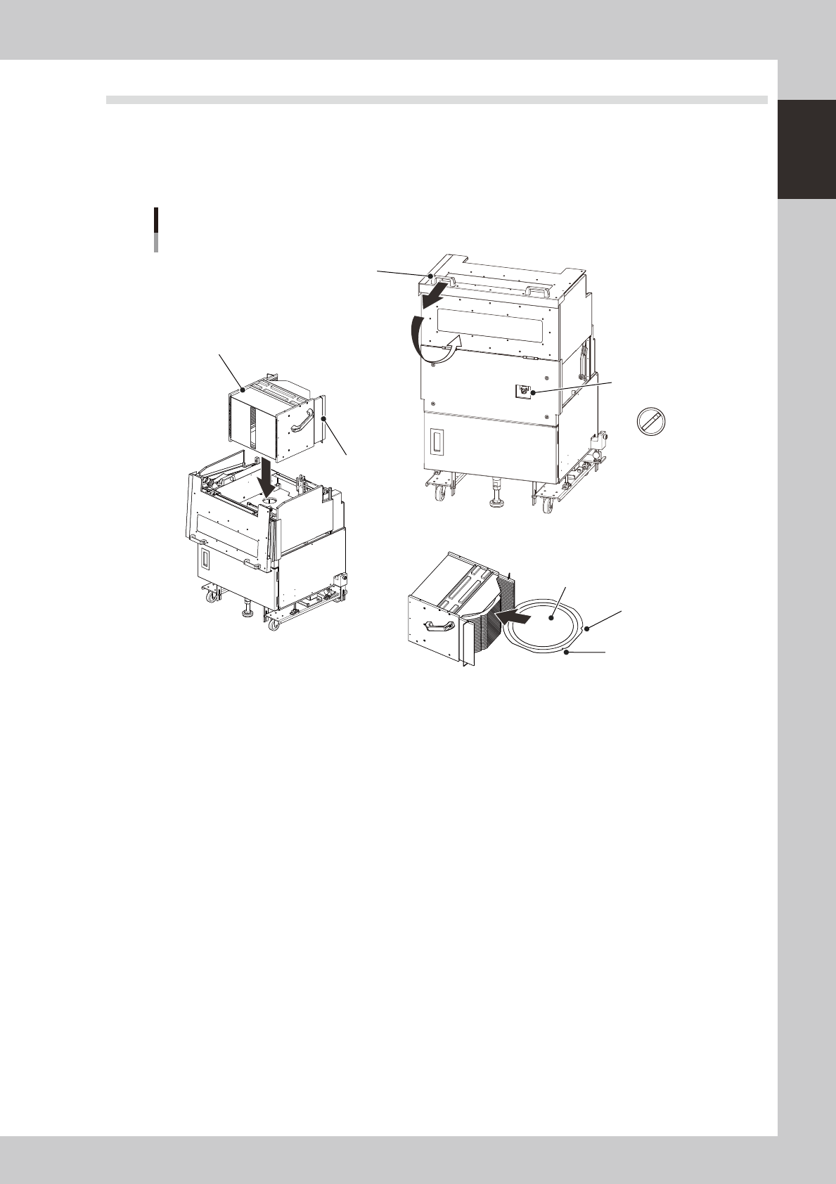
5.2 Supplying components from a wafer tray changer
When supplying components from a wafer tray changer, set it up as described below.
There are two methods for setting the wafer magazine.
• Insert a wafer component (dicing frame) directly into the magazine.
• Insert a wafer component set on a wafer pallet into the magazine.
A
U
T
O
S
E
T
U
P
Wafer tray changer
Component setup
Magazine position
selector switch
Magazine
Stopper
Cover open/close handle
N Setting the magazine
N Setting a wafer component
Notch
Flat side
Wafer component
23119-H0-00
n
Setting a 12-inch wafer component
1
Move the magazine to the wafer exchange position.
Set the magazine position selector switch to "SET UP".
e
2
Open the safety cover.
Press the emergency stop button and open the safety cover on this machine. Then pull the cover open/
close handle toward you to open the cover on the magazine side.
3
Set a wafer component as shown in the above figure.
4
Set the magazine.
Open the stoppers and set the magazine into the machine with the stoppers facing the machine.
5
Close the covers.
Close the covers on the magazine side and on the machine, then cancel emergency stop.
6
Return the machine to operation ready status.
Set the magazine position selector switch to "AUTO". The magazine will move to the operating position.
1-16
1
Part names and functions
n
When using wafer components other than 12 inch wafers
When using 6-inch or 8-inch wafers or wafer pallet components other than 12-inch wafer components, use the magazine
size attachment as shown below.
Wafer tray changer
Magazine set position
12-inch wafer magazine
Stopper
8-inch wafer magazine
6-inch wafer magazine
Knock pin
Magazine size attachment
Knock pin hole
23120-H0-00
c
1-17
1
Part names and functions
6.
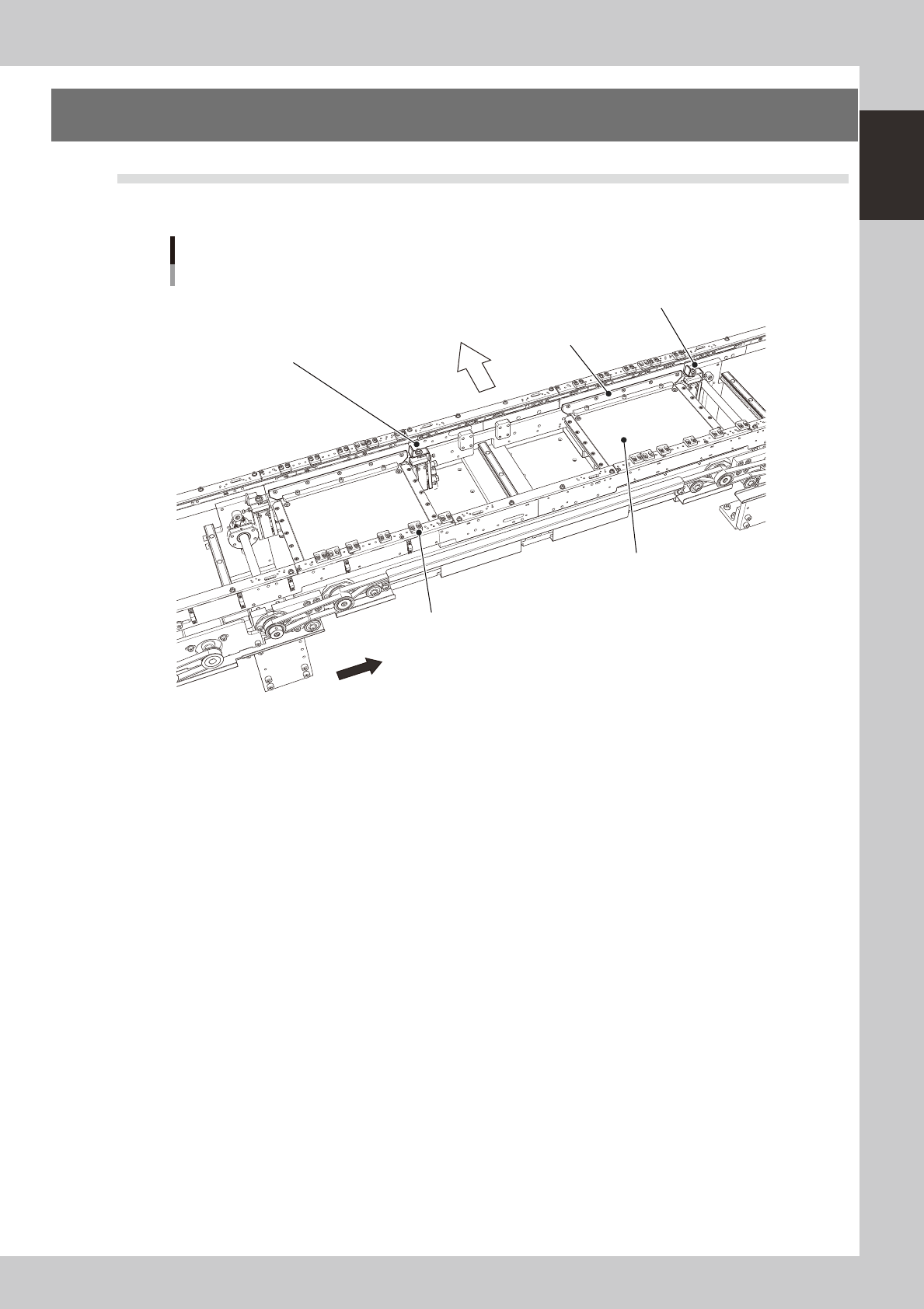
Conveyor unit
6.1
Conveyor unit
The conveyor unit used to clamp a board in mounting position is described below.
Conveyor unit
A-table main stopper
Front of machine
Direction of board flow
Push-up plate
Board hold plate (movable)
B-table main stopper
Clamp unit
23121-H0-00
• Main stopper
When a board is carried in on the conveyor, the main stopper halts travel of the board in the component mounting
position.
• Push-up plate
Clamps the board up against the board hold plates in conjunction with the clamp unit.
• Board hold plate (movable)
These plates hold the edges of the board from above when the board is clamped.
• Clamp unit
This moves up with the push-up plate and clamps the board by pushing it up against the board hold plates.