YSH20_Ope_E.pdf - 第77页
2-20 2 asic operation 3.2 Star ting the machine Proceed as follows to start the mac hine. 1 T urn the main power ON. T ur n on the main power switch at the front l ower right of the machine, by turning it to the right.…
2-19
2
asic operation
3.1 Pre-operation check
e
Check the following points before turning on the power.
w
WARNING
n
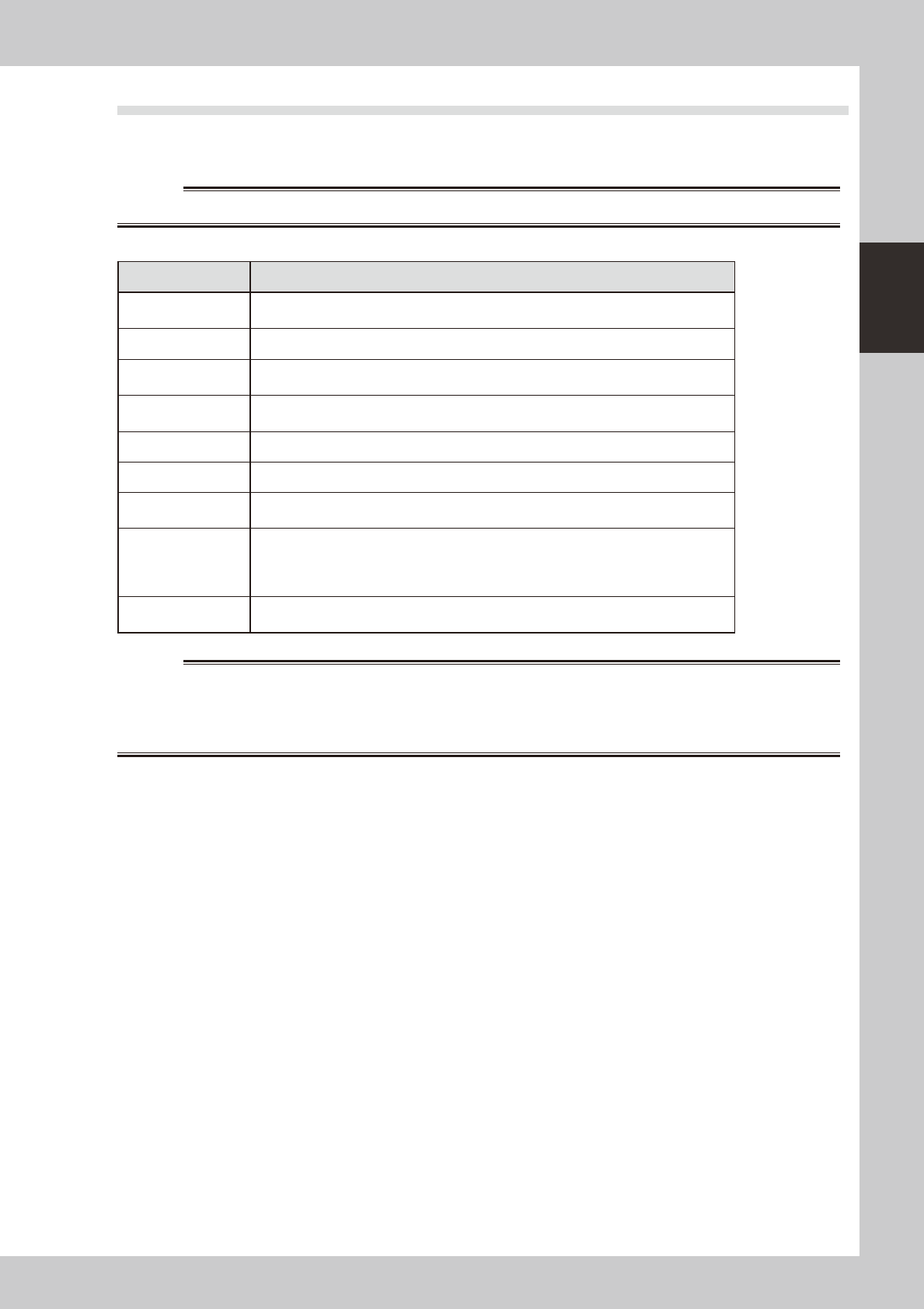
Pre-operation checklist
Check item Checkpoint
Power supply
Check that the specified power is connected to the power supply box located behind the
front lower right panel of the machine.
Safety cover Check that the covers are closed.
Signal light (signal
tower)
Check that the red lamp is lit.
Feeder (option) Check that feeders are securely attached to the feeder plate and are not tilted.
Check that no chips or debris adhere to the feeders.
Conveyor Check that no chips or debris are on the conveyor.
Head Check that each nozzle is correctly installed to the head.
Nozzle
Check that the nozzle tips are not nicked, solder does not adhere to the nozzle tips, and
nozzle spring-action is smooth.
Wafer tray changer
(option)
Check that the components (dicing frame or wafer pallet) are correctly set in place.
Check that the wafer unit (magazine) is correctly connected.
Check that the magazine door is closed.
Check that the magazine position selector switch is set to "AUTO".
Dipping station
(option)
Check that this unit is correctly installed on the feeder plate.
Check also that the wire harness is connected to the specified connector.
w
WARNING
2-20
2
asic operation
3.2 Starting the machine
Proceed as follows to start the machine.
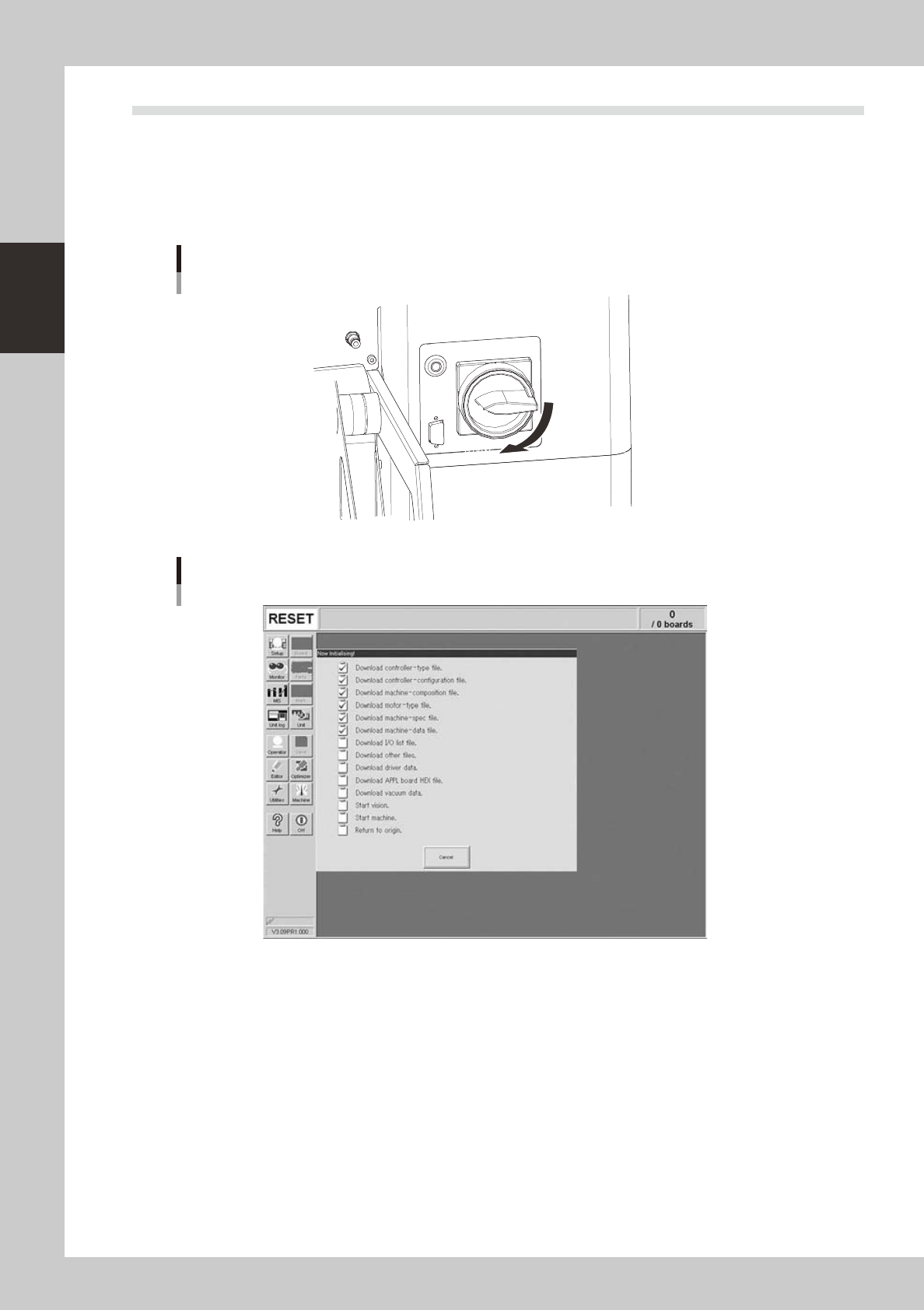
1
Turn the main power ON.
Turn on the main power switch at the front lower right of the machine, by turning it to the right. After the
system has started, the Initialization screen appears and the program necessary for machine operation
is loaded.
OFF
ON
Main switch
23202-H0-00
Initialization screen
24213-H0-00
2
Perform return-to-origin.
The return-to-origin dialog box appears. Press the [READY] button and follow the instructions on the
screen.
2-21
2
asic operation
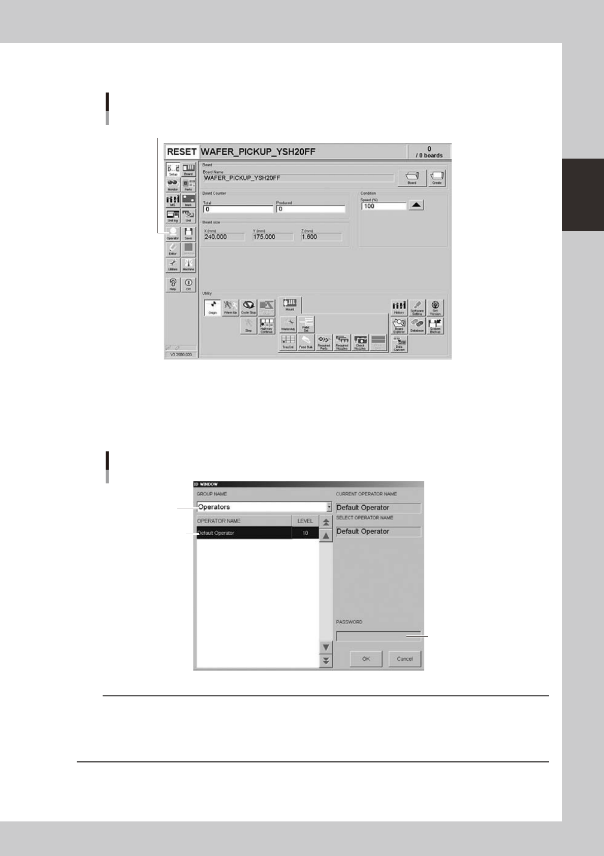
3
Press the [Operator] button.
The ID WINDOW dialog box appears for specifying the operator.
Press the [Operator] button to open the ID WINDOW.
[Operator] button
24214-H0-00
4
Specify the operator and enter the password.
As needed, the operator "Administrator" or "Operator" can be selected from the GROUP NAME list.
Select the group name and operator name, enter the password, and press the [OK] button. (Just press
the [OK] button if no password is set.) When the password is matched, the initial screen (Setup screen
before selecting a board) appears.
Select group name.
Enter password.
Select operator name.
Specifying the operator
24215-H0-00
TIP
Active menu buttons differ depending on the operation level setup. For example, when the machine is turned on with
the factory setup, the program starts up at an operation level called "Default Operator". This "Default Operator" level is
set to "Level 0" at the time of shipment to allow only basic operation items. This operation level can be changed as
needed. Operators and operation items can also be added and specified by setting the password and operation
level.