YSH20_Ope_E.pdf - 第55页
1-19 1 Part names and functions 7. Axis configuration The ser vomotor-controlled axis configuration and operating directions of this machine and wafer tray change are described below . n Axis configuration of this machin…
1-18
1
Part names and functions
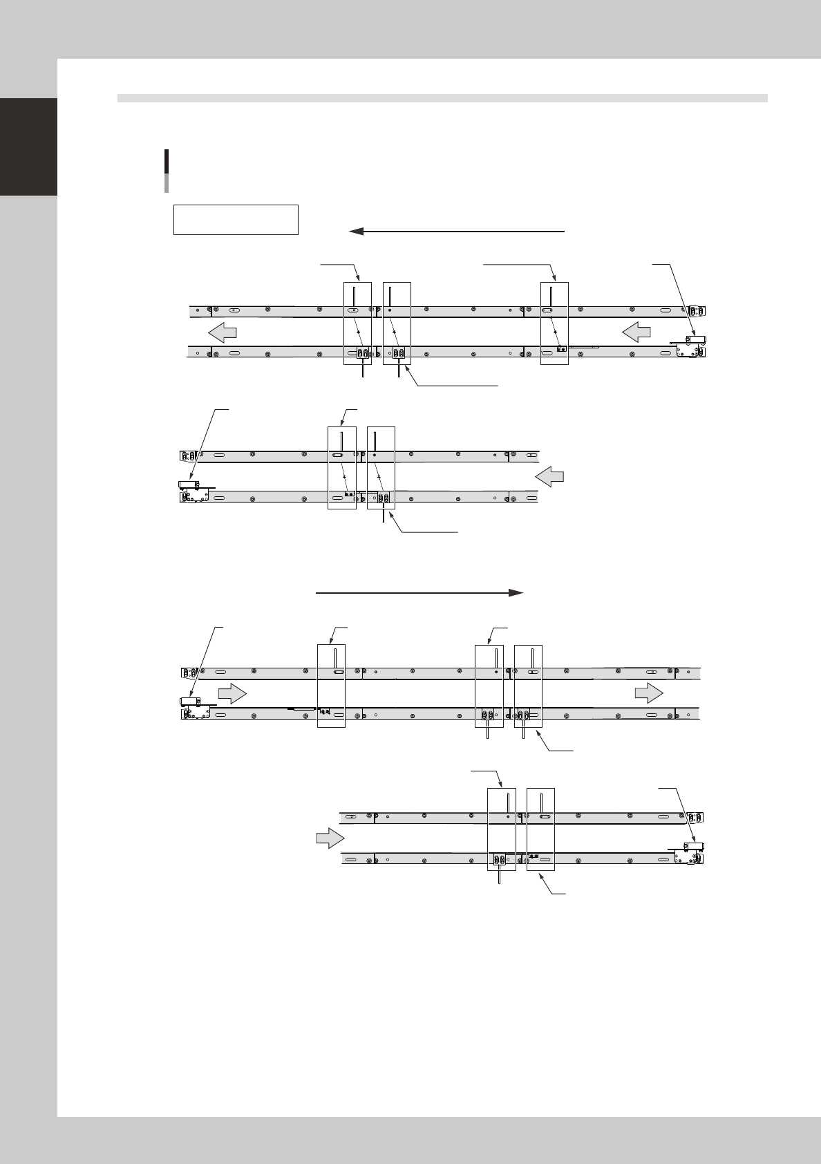
6.2 Conveyor sensor positions
The position of each board sensor on the conveyor is shown below.
Board sensor position
Direction of board flow
Direction of board flow
Board detection at entrance
[N 0100404]
Board detection at entrance
[N 01003F3]
Board detection at standby position
[N 0100405]
Board detection at standby position
[N 01003F1]
Board detection at stage A exit
[N 0100411]
Upper row: Sensor function
Lower row: [Address]
Board detection at stage A exit
[N 0100405]
Board detection at exit
[N 01003F3]
Board detection at exit
[N 0100404]
Board detection at stage B board clamp position
[N01003F2]
Board detection at stage B board clamp position
[N01003F2]
Board detection at stage A board clamp position
[N0100406]
Board detection at stage A board clamp position
[N0100406]
Board detection at stage B exit
[N 01003F1]
Board detection at stage B exit
[N 01003F5]
23122-H0-00
1-19
1
Part names and functions
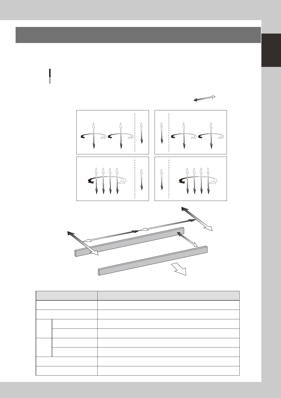
7. Axis configuration
The servomotor-controlled axis configuration and operating directions of this machine and wafer tray change
are described below.
n
Axis configuration of this machine
Plus direction
Minus direction
W1 axis
Axis configuration
Right-to-left board flow
RB2 axis
RB1 axis
N Head unit
N Main axes, Conveyor
A-table head unit
B-table head unit
FF head
4M head
ZB1
ZB2
RA2 axis
RA1 axis
ZA1
ZA2
CZB axis CZA axis
RB1 axis
ZB1 ZB2 ZB3 ZB4
RA1 axis
ZA1 ZA2 ZA3 ZA4
CZB axis CZA axis
YB axis
YA axis
XA axis
XB axis
Front of machine
23123-H0-10
n
Function of each axis
Axis Function
XA, XB Moves the head unit above the table in parallel with the board flow on the conveyor.
YA, YB Moves the head unit perpendicular to the board flow on the conveyor.
FF
RA1, RA2, RB1, RB2 Turns the nozzle shaft of each head.
ZA1, ZA2, ZB1, ZB2 Moves the component pick-and-place head of each head vertically.
4M
RA1, RB1, Turns the nozzle shafts (4 shafts) for each table simultaneously.
ZA1 to ZA4, ZB1 to ZB4 Moves the component pick-and-place head of each head vertically.
W1 Changes the conveyor width.
CZA, CZB Moves the fiducial camera unit vertically.
1-20
1
Part names and functions
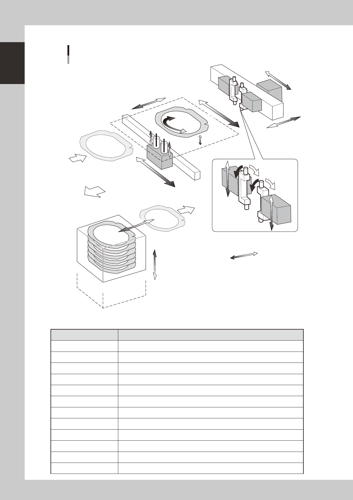
n
Axis configuration of wafer tray changer
Plus direction
Minus direction
Axis configuration
Wafer tray changer
LCX axis
LFX axisLFX axis
LCY axis
LZ axis
LH axisLH axis
LP1 axis
LR1 axis
LP2 axis
LR2 axis
LA axis
LE axis
LU1 axis
LU2 axis
LY axis
LX axis
Front of machine
23124-H0-00
n
Function of each axis
Axis Function
LZ Moves the magazine vertically.
LH Extracts a wafer from the tray changer and sets it on this machine.
LY Moves a wafer in the Y direction on this machine.
LX Moves the push-up pin unit in the X direction.
LCX Moves the wafer camera in the X direction.
LCY Moves the wafer camera and wafer pickup head in the Y direction.
LU1, LU2 Moves the push-up pin vertically.
LE Extends the dicing sheet to apply tension to it.
LFX Moves the wafer pickup head in the X direction.
LP1, LP2 Moves up or down when the wafer pickup head picks up a wafer.
LR1, LR2 Turns the two wafer pickup heads.
LA Turns a wafer.