4OM-1075-002.pdf - 第20页
Fig. 4A7 Rear View of Machine Fig. 4A8 Sectional View A-A ’ 1.3 Maintenance Spots Multi-Layer T ray Feeder #2 (Option) (5) Feeder Base (8) Fixed Camera Section (7) T eaching Plate Section (9) Head Section (1 1) Conveyor …
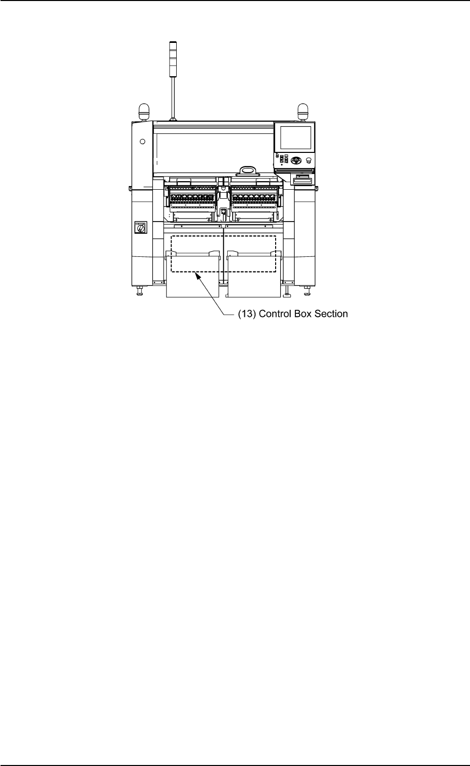
Fig. 4A6 Front View of Machine
1.3 Maintenance Spots
0206-003 1-6 AHB01ETRP
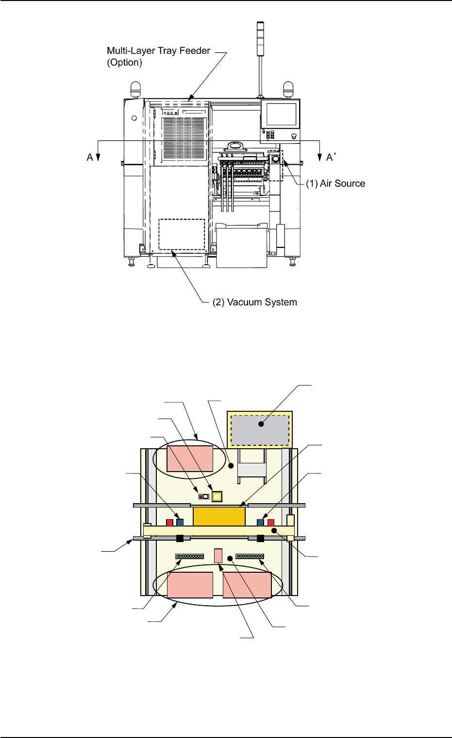
Fig. 4A7 Rear View of Machine
Fig. 4A8 Sectional View A-A’
1.3 Maintenance Spots
Multi-Layer Tray Feeder #2
(Option)
(5) Feeder Base
(8) Fixed Camera Section
(7) Teaching Plate Section
(9) Head Section
(11) Conveyor Section
(12) Nozzle Stocker Section
(5) Feeder Base
(4) Component Storage Box
(14) Frame
(12) Nozzle Stocker Section
(10) X/Y Beam Section
(9) Head Section
(6) P.C.B. Positioning Section
(P Conveyor)
(14) Frame
0206-003 1-7 AHB01ETRP
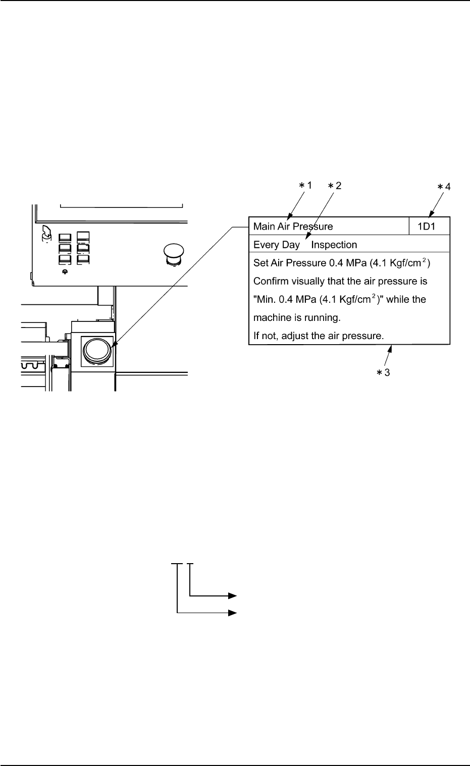
1.3.2 Understanding of Maintenance Items on Each Section
Clarified in this session are each individual spots of the machine to be
maintained.
Refer to "1.5 Maintenance Check List" for periodic maintenance.
View of Inspection, Cleaning, and Lubrication Spots (Example of
Identification)
Fig. 4A9
*1: Maintenance Spot
*2: Cycle and Contents of Maintenance
*3: Details of Maintenance
*4: Maintenance No.
These are used in "1.5 Maintenance Check List".
ID No. 1D 2
Number (0, 1, 2
• • • •
)
Cycle of Maintenance
1D : Every Day
1W : Every Week
1M : Every Month
3M : Every 3 Months
6M : Every 6 Months
1.3 Maintenance Spots
0206-003 1-8 AHB01ETRP