4OM-1075-002.pdf - 第46页
1.4 Maintenance Method 1.4.1 Replacement of Nozzle Change Cam • Detachment Procedure (1) T urn off the power supply . (2) Move the X/Y beam by hand such that the heads become reach- able. (3) Rotate the NC-axis cam origi…
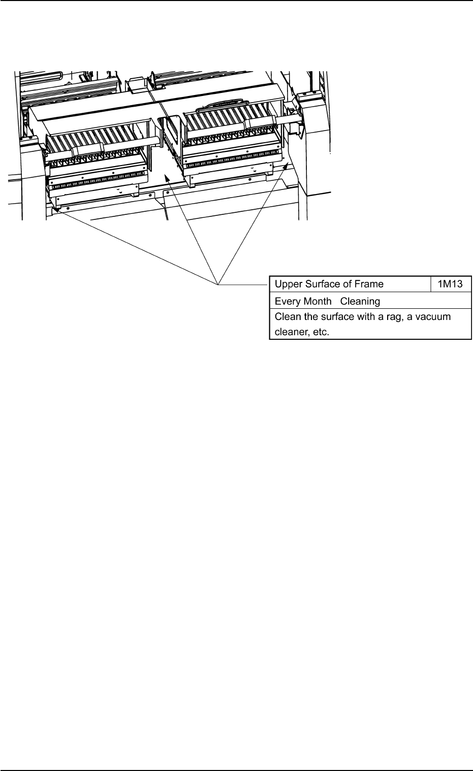
(14) Frame
Fig. 4A39
1.3 Maintenance Spots
0206-003 1-31 AHB01ETRP
1.4 Maintenance Method
1.4.1 Replacement of Nozzle Change Cam
• Detachment Procedure
(1) Turn off the power supply.
(2) Move the X/Y beam by hand such that the heads become reach-
able.
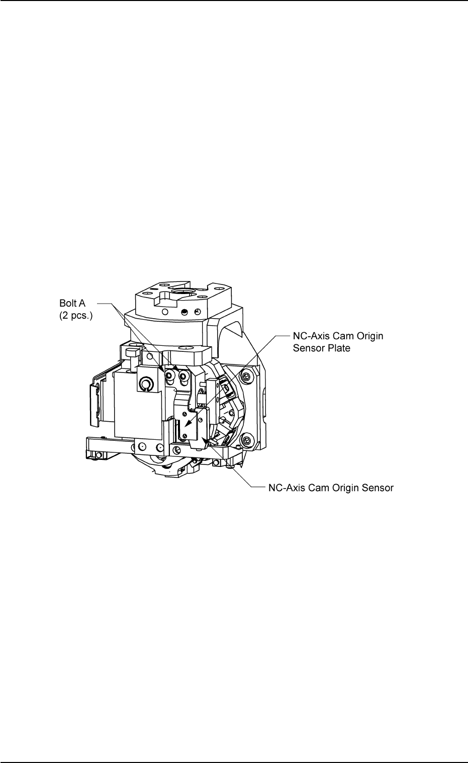
(3) Rotate the NC-axis cam origin sensor plate to the position where it
can easily be detached.
Cut two tie wraps with a pair of nippers.
Remove two bolts A with a hex-head wrench (2 mm) and detach
the NC-axis cam origin sensor.
Fig. 4A40
1.4 Maintenance Method
0206-003 1-32 AHB01ETRP
0308-004 1-33 AHB01ETRP
1.4 Maintenance Method
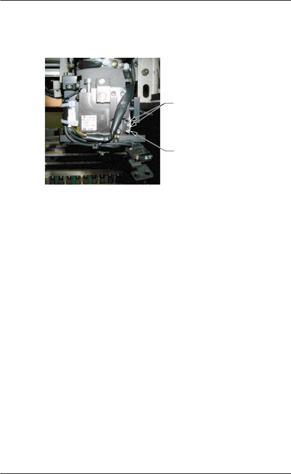
(4) Move down the NC-axis cam origin sensor.
Remove two Bolts B with a hex-head wrench (2 mm) and detach
the nozzle change cam.
Fig. 4A41
••
••
• Attachment Procedure
(1) Attach a new nozzle change cam with two Bolts B.
(2) Fasten the NC-axis cam origin sensor plate by temporarily tighten-
ing two Bolts A and arrange the cables with two tie wraps.
(3) Lubricate the nozzle change cam.
Wipe off old grease with a rag and apply a small amount of new
grease with a cotton swab, etc.
Bolts B
(2 pcs.)
Nozzle Change Cam
(Part No.: 630 094 1692)