4OM-1075-002.pdf - 第89页
0206-002 2-8-3 AHB01ETRP 2.3.2 During Pass Operation T able 4B3-3 Symptom (1 ) The LED of the [POWER ON] button illuminates in red and the following window opens. Fig. 4B9-1 Cause (1) An [EMERGENCY STOP] button was press…
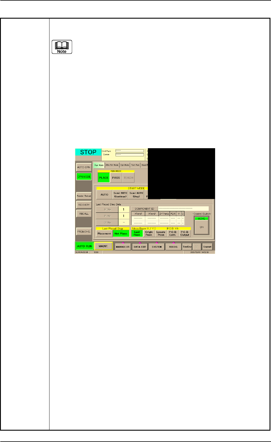
Table 4B3-2
(12) Check how the last component was placed when the operation was
interrupted.
The last placement step is indicated in the "Last Placed Step Data"
group box in the "OPN. MODE" window (submenu).
Check visually whether or not the relevant component is placed on
the P.C.B.
(13) Press the [Last Placed Pos.] button (entitled "Move Beam X/Y" in the
"OPN. MODE" window (submenu).
(14) Press the [RECOG.] button on the main menu bar and make the recog-
nition window (1/4 of the whole view at the upper right corner) appear.
(15) Press the [ON] button (entitled "MOVE"). In two seconds, press the [EN-
ABLE] button on the operation panel.
The last placement position is displayed as a recognition image.
Fig. 4B9 "OPN. MODE" Window (Last Step Confirmation)
(16) Check whether or not the component is placed. If not, select the [Place-
ment] button. If the component is already placed, select the [Not Place-
ment] button.
(17) Press the [ENABLE] button on the operation panel in 2 seconds after
the [Origin Pos.] and the [ON] button (entitled "MOVE"). The XY beam
returns to its origin.
(18) Press the [START] button on the operation panel. The "Warm Start"
operation is implemented.
(19) As for the P.C.B. produced through "Warm Start" operations, be sure to
confirm that all components are correctly placed.
0308-003 2-8-2 AHB01ETRP
2.3 [EMERGENCY STOP] Button Pressed
0206-002 2-8-3 AHB01ETRP
2.3.2 During Pass Operation
Table 4B3-3
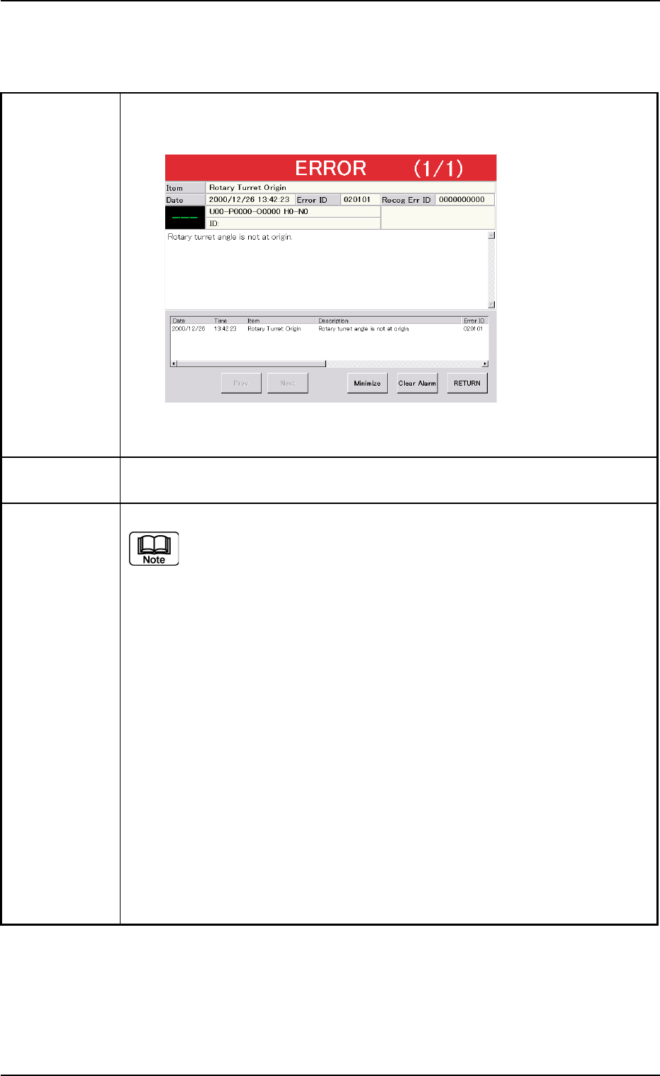
Symptom (1) The LED of the [POWER ON] button illuminates in red and the following
window opens.
Fig. 4B9-1
Cause (1) An [EMERGENCY STOP] button was pressed.
Remedy (1) Press the [RETURN] button.
Remove the P.C.B. in the middle of passing inside the machine if any.
(2) Turn the [EMERGENCY STOP] button clockwise to release the locked
condition.
(3) Hold down the [POWER ON] button for more than 1 second to re-supply
power to the machine.
• When the LED of the [POWER ON] button illuminates in yellowish green,
it indicates that the power is supplied to the machine.
When the LED is kept red, re-check the cause and remove it.
(4) Press the [ALL] button (entitled "ZERO") in the "AUTO OPN." window. In 2
seconds, press the [ENABLE] button on the operation panel to zero all
devices.
2.3 [EMERGENCY STOP] Button Pressed
2.4 Continuous Operation Disabled during Component Placement
2.4 Continuous Operation Disabled during Compo-
nent Placement
Table 4B3-4
Symptom The continuous operation became impossible during component placement.
No error message is issued on the touch screen and the machine is kept in
the "RUN" or the "WAIT" mode without any movement.
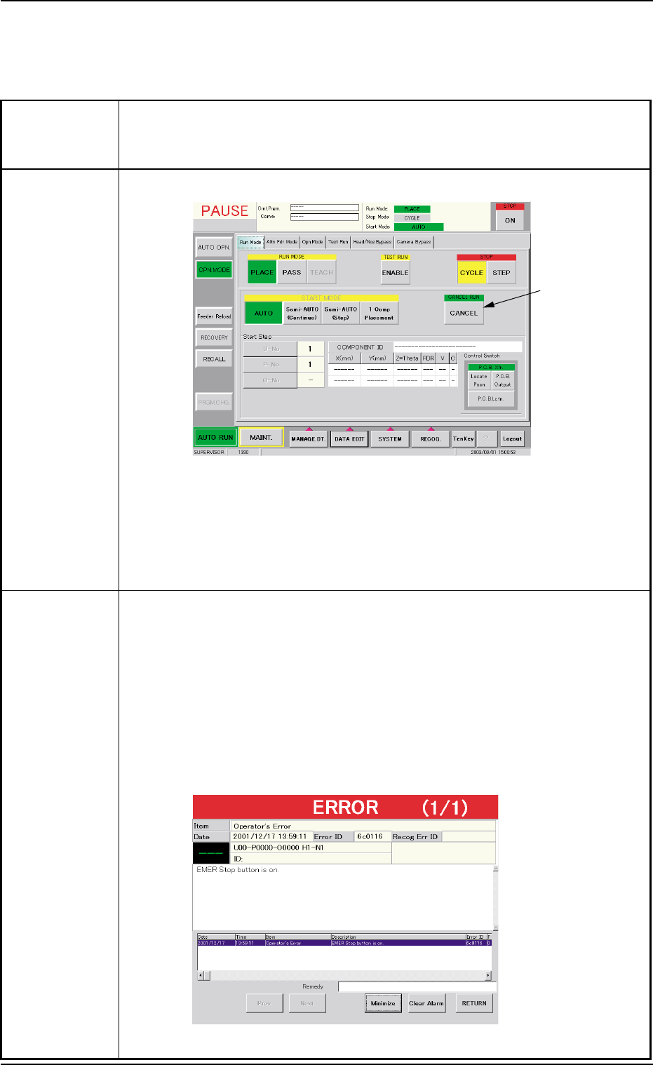
Cause (Cause 1) The [CANCEL] button was pressed.
Fig. 4B10 "Run Mode" Tab Sheet ("PAUSE" Mode)
(Cause 2) A timing error has occurred.
An interlock error has occurred.
The machine stopped at an emergency although the cause is un-
known.
Remedy When a normal restart operation is performed after the continuous operation
has become impossible during component placement, the P.C.B. in the middle
of process is discharged to the output machine, producing a defective P.C.B.
Therefore, it is required to perform the following "Warm Start" operation to set
the machine to its normal condition.
(1) Press an [EMERGENCY STOP] button.
The "ERROR" window opens.
(2) Confirm that the message "EMER Stop button is on." is issued on the
screen.
Fig. 4B11 "ERROR" Window
0308-003 2-8-4
AHB01ETRP
[CANCEL]
Button